Local testing and operating sequence
Tests and Measurements
............................................................................................................................................................................................................................................................
PN 8DG08136CAAA
Issue 1 March 2008
3-57
............................................................................................................................................................................................................................................................
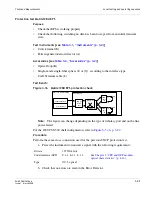
Figure 3-19 Back panel electrical connectors location and pinout
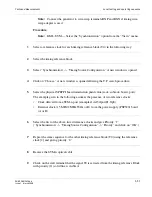
5. Fan 19” alarm test
Procedure
a. Extract one FAN unit
EML-USM — Double-click on the involved FAN.
•
Verify that the RUM alarm turns ON.
b. Repeat the procedure on the other FAN.
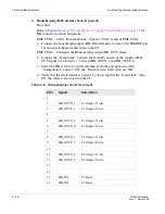
17
HK_IN3
# 3 Input
18
HK_IN4
# 4 Input
19
HK_IN5
# 5 Input
20
HK_IN6
# 6 Input
21
HK_IN7
# 7 Input
22
HK_IN8
# 8 Input
23
24
HK_REF
Voltage reference of input housekeeping
25
case
GND
Electrical ground - Case
#Pin
Signals
Description
6 9
1
5
8
1
1 5
9
2 5
1 4
1 3
1
8
1
1 5
9
2 5
1 4
1 3
1
1 3
+
-
1 3
+
-
PSFA
PSFB
AUX CHANNELS
STUPA
STUPB
HOUSEKEEPING
SHELF ID
RL
RA
Summary of Contents for 1850 TSS-320
Page 6: ... List of figures v i PN 8DG08136CAAA Issue 1 March 2008 ...
Page 8: ... List of tables v i i i PN 8DG08136CAAA Issue 1 March 2008 ...
Page 16: ... Safety rules Safety 1 4 PN 8DG08136CAAA Issue 1 March 2008 ...
Page 138: ... Other technical support services Technical Support A 14 PN 8DG08136CAAA Issue 1 March 2008 ...
Page 140: ... Glossary GL 2 PN 8DG08136CAAA Issue 1 March 2008 ...


