Point-to-point measures list and operating sequence
Tests and Measurements
............................................................................................................................................................................................................................................................
PN 8DG08136CAAA
Issue 1 March 2008
3-63
............................................................................................................................................................................................................................................................
STATION-A
........................................................................................................................................................................................................................
5
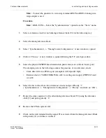
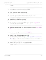
With the pattern generator, send a fixed PRBS sequence
........................................................................................................................................................................................................................
6
Check that the error detector has read no errors.
........................................................................................................................................................................................................................
7
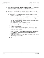
Increase the optical attenuation till errors are read on the error detector.
........................................................................................................................................................................................................................
8
Reduce attenuation until no errors are read.
........................................................................................................................................................................................................................
9
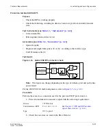
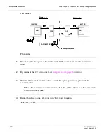
Disconnect the optical cable from the STM-n input port (point A in
Figure 28
) and
connect it to the power meter input.
........................................................................................................................................................................................................................
10
Margin level must be minimum 4 dB better than the values reported in
para 4.7 on page
87.
........................................................................................................................................................................................................................
11
Turn-on the laser through the CT (see
para. 4.6 on page 86
).
........................................................................................................................................................................................................................
12
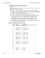
Wait for 180 sec. and then read the Rx optical power.
The difference between the Rx optical power [see
“Rx Optical “line port” power check”
(p. 3-59)
] and the Rx optical power when introducing attenuation (as above explain) is the
“link margin.”
........................................................................................................................................................................................................................
13
Repeat the check on the other port with “line port” function.
........................................................................................................................................................
E
N D
O
F
S
T E P S
Summary of Contents for 1850 TSS-320
Page 6: ... List of figures v i PN 8DG08136CAAA Issue 1 March 2008 ...
Page 8: ... List of tables v i i i PN 8DG08136CAAA Issue 1 March 2008 ...
Page 16: ... Safety rules Safety 1 4 PN 8DG08136CAAA Issue 1 March 2008 ...
Page 138: ... Other technical support services Technical Support A 14 PN 8DG08136CAAA Issue 1 March 2008 ...
Page 140: ... Glossary GL 2 PN 8DG08136CAAA Issue 1 March 2008 ...

