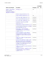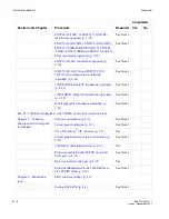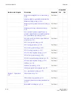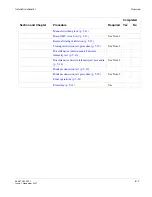
Replacement methods
Backplane pin replacement
............................................................................................................................................................................................................................................................
365-372-304R7.1
Issue 1, November 2007
D - 7
............................................................................................................................................................................................................................................................
Replacement methods
Background
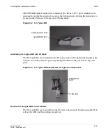
Connector pins are designed to withstand a considerable removal force. An impact-type
tool is used to generate a controlled removal force. Similarly, proper insertion of a press-fit
connector pin is done with an impact-type tool to control the insertion forces and not
damage adjacent pins.
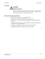
Precautions
Read the following Important statements before proceeding:
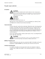
Important!
Any press-fit connector pin may be removed and replaced
one time
in
the 1665 DMX backplane. A second removal and replacement in the same plated-
through hole may not meet the long-term reliability objectives. If a replacement is
needed for a previously replaced connector pin, contact your next level of support
before proceeding.
Important!
Protect the surrounding area from any debris which may be generated
during the pin removal and replacement.
Procedure for METRAL™ pins
Use the procedure below to replace pins when required:
........................................................................................................................................................................................................................
1
Verify that the problem cannot be fixed using a simple repair procedure.
........................................................................................................................................................................................................................
2
Secure the proper tool kit.
........................................................................................................................................................................................................................
3
Read the tool kit instructions before beginning.
........................................................................................................................................................................................................................
4
Plan and write out a “Method of Procedure” specific to your location.
........................................................................................................................................................................................................................
5
Follow the instructions provided to remove the damaged pin.
........................................................................................................................................................................................................................
6
Install the replacement pin.
Summary of Contents for Data Multiplexer Explore 1665
Page 8: ... Contents v i i i 365 372 304R7 1 Issue 1 November 2007 ...
Page 12: ... List of figures x i i 365 372 304R7 1 Issue 1 November 2007 ...
Page 16: ... List of tables x v i 365 372 304R7 1 Issue 1 November 2007 ...
Page 24: ... About this document x x i v 365 372 304R7 1 Issue 1 November 2007 ...
Page 272: ... Final operations Operational tests 5 2 2 365 372 304R7 1 Issue 1 November 2007 ...
Page 326: ... Cleaning pluggable optics modules Fiber cleaning B 1 4 365 372 304R7 1 Issue 1 November 2007 ...
Page 408: ...I N 4 365 372 304R7 1 Issue 1 November 2007 Index ...

