OmniAccess 6000: Installation Guide
16
Part 031639-00
May 2005
z
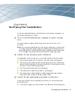
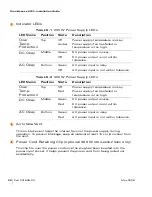
The fan tray Fan Status LED is still solid green.
z
One the line card:
z
The Power LED is still solid green.
z
The Status LED is solid green.
z
On the supervisor card:
z
The power LED is still solid green.
z
The Status and Active/Standby LEDs are solid green.
z
The Utilization LED panel reflects the expected level of usage.
In a typical power-on test performed after initial installation, a single blinking LED
will indicate utilization of under 1%.
N
OTE
—
For more information on LED behavior, refer to the individual chapters
for the specific modules.
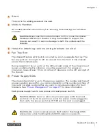
Once the system has passed the initial power-up test:
z
Connect appropriate network cables (see
“The Supervisor Card”
and
“The
Line Cards”
for port and cable information).
You are now ready to perform the initial setup as described in the
Alcatel Quick
Start Guide
(which is
included in the Accessory Kit).
4
5
Summary of Contents for OmniAccess 6000
Page 1: ...i OmniAccess 6000 Wireless LAN Switch Installation Guide TM ...
Page 10: ...OmniAccess 6000 Installation Guide x Part 031639 00 May 2005 ...
Page 14: ...OmniAccess 6000 Installation Guide xiv Part 031639 00 May 2005 ...
Page 18: ...OmniAccess 6000 Installation Guide 4 Part 031639 00 May 2005 ...
Page 27: ...Installing the Chassis 13 Chapter 2 ...
Page 28: ...OmniAccess 6000 Installation Guide 14 Part 031639 00 May 2005 ...
Page 36: ...OmniAccess 6000 Installation Guide 22 Part 031639 00 May 2005 ...
Page 48: ...OmniAccess 6000 Installation Guide 34 Part 031639 00 May 2005 ...
Page 74: ...OmniAccess 6000 Installation Guide 60 Part 031639 00 May 2005 ...


