The Supervisor Card
39
Chapter 6
See the
Alcatel AOS-W User’s Guide
for information on using the features
available through this port.
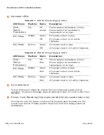
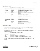
Utilization LEDs
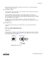
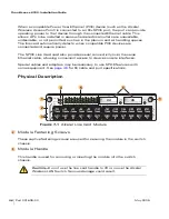
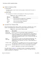
The supervisor card has a bank of five utilization LEDs. While booting, these
LEDs light in sequential fashion.
During operation, these LEDs light to indicate the level of activity in a
functioning module. Each LED from left to right represents an increment of
20% in the activity of the supervisor card. When all five LEDs are lit, the SCM
is functioning at 100% capacity.
The right-most of the lit LEDs will blink to verify the supervisor card is
operating properly. No LEDs will be lit if the module is in standby mode or not
functioning.
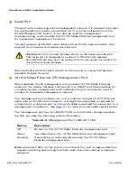
Reset button
Only push the reset button when directed to do so by Alcatel technical
support.
Port & Cable Specifications
Serial Port
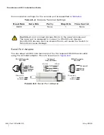
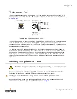
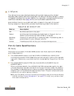
The serial port is located on the front panel of the supervisor card. The port’s
RJ-45 female connector accepts an RS-232 serial cable with a male connector.
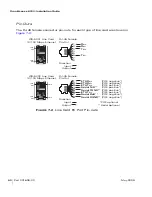
Pin-outs are shown in
Figure 6-2
:
F
IGURE
6-2
Serial Port
7
8
Serial
Console Port
1
2
3
4
5
6
7
8
TxD
TGND
RGND
RxD
RJ-45 Female
Pin-Out
Direction
Input
Output
Summary of Contents for OmniAccess 6000
Page 1: ...i OmniAccess 6000 Wireless LAN Switch Installation Guide TM ...
Page 10: ...OmniAccess 6000 Installation Guide x Part 031639 00 May 2005 ...
Page 14: ...OmniAccess 6000 Installation Guide xiv Part 031639 00 May 2005 ...
Page 18: ...OmniAccess 6000 Installation Guide 4 Part 031639 00 May 2005 ...
Page 27: ...Installing the Chassis 13 Chapter 2 ...
Page 28: ...OmniAccess 6000 Installation Guide 14 Part 031639 00 May 2005 ...
Page 36: ...OmniAccess 6000 Installation Guide 22 Part 031639 00 May 2005 ...
Page 48: ...OmniAccess 6000 Installation Guide 34 Part 031639 00 May 2005 ...
Page 74: ...OmniAccess 6000 Installation Guide 60 Part 031639 00 May 2005 ...

