background image

Getting Started

System Hardware Specifications

10

255-700-161

PacketStar

®

 PSAX 2300 Multiservice Media Gateway Installation Guide

, Issue 4

Power Supply Module Specifications

The specifications for the PSAX 2300/4500 -48 V dc Power Supply module are given 
in Table 5. 


Stratum 3–4 Module Specifications

The specifications for the PSAX 2300 Stratum 3–4 module are given in Table 6.

Operating altitude range

60 meters (197 feet) below sea level to 4,000 meters (13,123 
feet) above sea level

Storage temperature range

-40° to 70° C (-40° to 158° F)

Storage humidity range

0% to 90% noncondensing

Table 4.  System Environmental Specifications (Continued)

Specification

Description

Table 5.  -48 V dc Power Supply Module Specifications

Specification

Description

Slot Configuration

Two dedicated slots below module slots

Power

Voltage range:

 -42.5 to -56.5 V DC

Rated current:

 12.5 A maximum per module

Maximum input power:

  470 W (1605 BTU/hr) maximum per chassis 

Maximum output power:

  500 W 

Circuit protection:

 Two 10 A, wire-type fast acting, black/white alarm 

indicating, fuses

Dimensions

9.55 cm H x 26.67 cm D x 21.27 cm W
(3.76 in. H x 10.50 in. D x 8.375 in. W)

Weight

2.37 kg (5.25 lb) 

Units per system

Two required for redundancy

Connector

Two screw-type terminals on the rear panel

Wire/cable size 
(PSAX 2300)

Power feed:

 two pair of 3.3–2.1 mm

2

 (#12–14 AWG) stranded recom-

mended

Frame ground:

 up to 5.3 mm

2

 (#10 AWG) stranded recommended.

Table 6.  Stratum 3–4 Module Specifications

Specification

Description

Slot configuration

Front two middle slots labeled 

A

 and 

B

Dimensions

15.8 cm H x 1.6 cm W x 24.1 cm D
(6.2 in. H x 0.6 in. W x 9.5 in. D)

Weight

0.22 kg (0.5 lb) 

Units per system

2 required for redundancy

Power consumption

12 W per pair

Synchronization source

Internal or external

Summary of Contents for PacketStar PSAX 2300

Page 1: ...PacketStar PSAX 2300 Multiservice Media Gateway Installation Guide for PacketStar PSAX Multiservice Media Gateways 255 700 161 Issue 4 April 2008 ...

Page 2: ...uced distributed or altered in any fashion by any entity either internal or external to Alcatel Lucent except in accordance with applicable agreements contracts or licensing without the express written consent of Alcatel Lucent and the business management owner of the material Trademarks All trademarks and service marks specified herein are owned by their respective companies ...

Page 3: ...nce xv Electromagnetic Compatibility Compliance xv Telecommunications Compliance xv Regulatory Statements xv USA Regulatory Statements xv FCC Part 15 xv FCC Part 68 xvi Underwriters Laboratories UL 1950 xvii Canadian Regulatory Statements xvii ICES 003 xvii NMB 003 xvii CS 03 Issue 8 xvii SH 03 Version 8 xvii European Union Regulatory Statement xviii CE Marking xviii EN 300 386 2 xxi Japanese Regu...

Page 4: ...tel Lucent Products 3 For More Information 3 About the PacketStar PSAX Product Family 3 PSAX 1000 Multiservice Media Gateway 3 PSAX 1250 Multiservice Media Gateway 4 PSAX 2300 Multiservice Media Gateway 4 PSAX 4500 Multiservice Media Gateway 4 Comments on This Guide 5 Getting Started 7 Overview of This Section 7 Using the Installation Checklist 7 Product Modification or Repair 7 System Hardware Co...

Page 5: ...nstalling the PSAX 2300 System 17 Overview of This Section 17 Before You Begin 17 Installing the Hardware 18 Attaching the Mounting Brackets to the Chassis 18 Mounting the Chassis 22 Grounding the Chassis 24 Connecting the Facility Power Cables 25 Installing the Common Equipment Modules 28 Installing the Power Supply Modules 28 Installing the Stratum 3 4 Modules 29 Installing the Stratum 3 4 Modul...

Page 6: ...Maintenance 45 Overview of This Section 45 Shutting Down the System 45 Removing Modules from the Chassis 46 Removing a DC Power Supply Module 46 Removing the Stratum 3 4 Module 46 Removing the Stratum 3 4 Module 46 Removing an I O or a CPUn Module 47 Removing an I O Module or a CPU2 Module 47 Removing a Server Module 49 Removing the Alarm Module 50 Replacing Blank Faceplates 51 Installing Blank I ...

Page 7: ...TUS CONTROL Connector 62 B Orderable Parts 65 Overview of This Appendix 65 Blank Faceplate Modules 65 Replacement Air Filters 65 Replacement Fuses 66 Orderable Cables 66 C Module Information 69 Overview of This Appendix 69 Performance and Power Specifications for Modules 69 Module Connections 74 Interface Types by I O Module 77 Index 83 Installation Checklist Checklist 1 Overview of This Section C...

Page 8: ... V dc Power Supply Module into the Chassis 28 14 Securing the Power Supply Module to the Chassis 29 15 Installing the Stratum 3 4 Module 30 16 Locking Tab on the CPUn Module Faceplate 32 17 Locking Tab on Alarm Module Faceplate 33 18 Status Indicators on the 48 V dc Power Supply Module 39 19 Locking Tab on the I O and Server Module Faceplate 42 20 Locking a Module in the PSAX 1000 Chassis 48 21 Lo...

Page 9: ...List of Figures 255 700 161 ix PacketStar PSAX 2300 Multiservice Media Gateway Installation Guide Issue 4 ...

Page 10: ...nments 57 17 CPU4 Module ETHERNET1 and ETHERNET2 Connector Pin Assignments 58 18 CPU2 Module CONSOLE Connector Pin Assignments 58 19 CPU2 Module ETHERNET Connector Pin Assignments 59 20 RJ 12 to DB9 Adapter Pin Assignments 59 21 RJ 12 to DB25 Adapter Pin Assignments 59 22 Stratum 3 4 Module RJ 45 Connector Pin Assignments 60 23 ALARM Connector Pin Assignments and Cable Pigtail Color Code COMCODE 3...

Page 11: ...X 2300 Multiservice Media Gateway Installation Guide Issue 4 Checklist 4 Applying Power to the System Checklist 3 Checklist 5 Installing and Connecting I O and Server Modules Checklist 4 Checklist 6 Configuring and Testing the System Checklist 4 ...

Page 12: ...List of Tables xii 255 700 161 PacketStar PSAX 2300 Multiservice Media Gateway Installation Guide Issue 4 ...

Page 13: ...eir respective owners APX 8000 CellPipe and ConnectStar are trademarks and 7R E ConnectReach STINGER PacketStar Navis Lucent Lucent Technologies Alcatel Lucent and the Alcatel Lucent logo are registered trademarks of Alcatel Lucent Other product and brand names mentioned in this guide are trade marks or registered trademarks of their respective owners Notices The information in this document is fo...

Page 14: ...is Use of other air filters will void your equipment warranty WARNING Damage to the module and or chassis that is caused by excessive force when installing the modules will void your equipment warranty WARNING Shipping the chassis with I O server or CPU modules installed may cause dam age to the chassis and the modules Damage to any of the components in the sys tem resulting from improper shipping...

Page 15: ...rope EN 55024 1998 A1 2001 A2 2003 Europe VCCI Class A Japan CISPR 22 4th Ed 2003 A1 2004 International CISPR 24 1st Ed 1997 A1 2001 A2 2002 International Telecommunications Compliance FCC Part 68 USA CS 08 Issue 8 SH 03 Version 8 Canada ETSI TBR 12 1993 A1 1996 Europe ETSI TBR 13 1996 Europe ETSI TBR 24 1997 Europe JATE Japan Regulatory Statements USA Regulatory Statements FCC Part 15 This equipm...

Page 16: ...phone network interface jack is built into this equipment and is compatible with interconnections that are Part 68 compliant 3 The REN for the 4 Port Voice 2 Wire Office module when used in this equipment is 0 7B 4 If this equipment causes harm to the telephone network the telephone company will notify you in advance that temporary discontinuance of service might be required But if advance notice ...

Page 17: ...e loop which is used by the device to prevent overloading The termination on a loop may consist of any combination of devices subject only to the requirement that the total of the REN of all devices does not exceed 5 The REN for the 4 Port Voice 2 Wire Office module when used in the PSAX system is 0 7B SH 03 Version 8 AVIS Le présent matériel est conforme aux spécifications techniques d Indus trie...

Page 18: ...ar PSAX 1000 48 V dc og 220 v veksel strøm PSAX 1250 48 V dc og 220 v vekselstrøm PSAX 2300 og PSAX 4500 Multiservice Media Gateways overholder kravene i følgende EU direktiver Lavspændingsdirektivet 72 23 EEC EMC direktivet 89 336 EEC Direktivet om radio og teleterminaludstyr 1999 5 EC Alcatel Lucent PacketStar PSAX Multiservice Media Gateways anvendt i EØS Europæiske Økonomiske Samarbejde skal f...

Page 19: ...ου Ίντερνετ https support lucent com portal olcsHome do Euroopan unionin sääntelystandardi CE merkintä Alcatel Lucent vakuuttaa täten että PacketStar PSAX 1000 48 V dc ja 220 V vaih tovirtaa PSAX 1250 48 V dc ja 220 V vaihtovirtaa PSAX 2300 ja PSAX 4500 Multiservice Media Gatewayt täyttävät seuraavien neuvoston direktiivien keskeiset vaatimukset ja asiaankuuluvat määräykset Pienjännite 72 23 EY Sä...

Page 20: ...reti E1 E3 STM 1 e STM 4c Le dichiarazioni di conformità CE possono essere stampate o visionate presso il seguente sito Internet di pubblico accesso https support lucent com portal olcsHome do Norm van de Europese Unie CE markering Alcatel Lucent verklaart hierbij dat de PacketStar PSAX 1000 48 V dc en 220V wisselstroom PSAX 1250 48 V dc en 220V wisselstroom PSAX 2300 en PSAX 4500 Multi Service Me...

Page 21: ...asarelas de medios multiservicio Alcatel Lucent PacketStar PSAX Multiservice Media Gateways desplegadas en el área económica europea European Economic Area EEA están destinadas a conectarse en redes E1 E3 STM 1 y STM 4c Las declaraciones de conformidad de la CE pueden verse o imprimirse en el siguiente sitio Internet de acceso público https support lucent com portal olcsHome do Europeiska unionens...

Page 22: ...d operating the PacketStar PSAX Multiservice Media Gateways follow the safety guidelines provided in the printed PacketStar PSAX Multiservice Media Gateway Safety Guidelines which accompanies this product to help prevent serious personal injury and damage to the PSAX equipment Please read all warnings and instructions supplied before beginning installation or configuration of the PSAX equipment In...

Page 23: ... discharge through it instead of dis charging on the cabinet Floor Covering Be sure that the room has antistatic flooring conductive mat carpeting or tiles to minimize static buildup as you walk across the room Follow these guidelines for installing and maintaining proper flooring The use of grounding foot straps is recommended while walking in rooms provid ing antistatic flooring Foot straps prov...

Page 24: ...inimize contact between clothing and electronic devices Handling Chassis Modules and Components Follow these guidelines for proper installation and handling of the PSAX system hardware to minimize ESD damage Remove the chassis modules and components from their shipping containers immediately before you are ready to install them When installing modules and components use wrist straps connected to a...

Page 25: ...he PSAX 2300 system Shutting down the PSAX 2300 system Removing modules from the installed PSAX 2300 system System maintenance Shipping the system Note If you are installing a new unconfigured PSAX system for the first time you should read through this guide and the PacketStar PSAX Multiservice Media Gateway User Guide before beginning the installation process Audience for This Guide The informati...

Page 26: ... data you enter Table 2 shows how each typographical convention is used Icons and Symbols Refer to the procedures within this guide for important safety information and proper procedures Standard icons and symbols to alert you to dangers warnings cautions and notes are described as follows Table 2 Text Conventions Appearance How it is used SANS SERIF BOLD ALL CAPS Labels on module panels chassis f...

Page 27: ...rranty Registration Information which accompanied your shipment for instructions on obtaining support in your area About Alcatel Lucent Products For More Information To learn more about the PacketStar PSAX family of Multiservice Media Gateways and the complete line of Alcatel Lucent products visit our Web site at http www lucent com About the PacketStar PSAX Product Family Alcatel Lucent provides ...

Page 28: ...yond 600 Mbps Supporting 10 slots 19 inch chassis or 14 slots 23 inch chassis for I O and server modules with a full range of interfaces such as DS0A DS1 E1 DS3 E3 OC 3 OC 3c STM 1 OC 12c STM 4c 10 100BASE T Ethernet and serial the PSAX 1250 system is a cost effective access switch solution for interworking with legacy equipment PSAX 2300 Multiservice Media Gateway The PacketStar PSAX 2300 Multise...

Page 29: ...e carrier network can transition traffic from a large number of network customers over high speed DS1 E1 IMA DS3 E3 OC 3 OC 3c STM 4c and OC 12c STM 4c trunks into the ATM core managing the whole quickly and efficiently down to the individual permanent virtual circuit Through the use of the latest DSP voice technology the PSAX 4500 system supports advanced voice traffic over ATM VToA services for ...

Page 30: ...About This Guide Comments on This Guide 6 255 700 161 PacketStar PSAX 2300 Multiservice Media Gateway Installation Guide Issue 4 ...

Page 31: ... Repair Do not make electrical or mechanical modifications to any of the components in the PSAX 2300 system Alcatel Lucent is not responsible for the safety or the perfor mance of a modified Alcatel Lucent product Do not remove or attempt to repair or modify any components inside the PSAX 2300 chassis Do not attempt to repair or modify any failed I O or server modules Modifying or tampering with P...

Page 32: ...chassis One RJ 12 to DB25 male cable adapter workstation to console cable Figure 2 PacketStar PSAX 2300 Multiservice Media Gateway 10 A FA IL no n redu nd an t AC TIVE Po wer Su pp ly 48 V Po wer Su pp ly 48 V AC TIVE DS1 IM A FA IL LO S 1 6 5 4 3 2 AC TIVE DS1 Enh FA IL LO S 1 6 5 4 3 2 AC TIVE DS1 Enh FA IL LO S 1 6 5 4 3 2 AC TIVE DS1 ATM FA IL LO S 1 6 5 4 3 2 AC TIVE DS1 CE FA IL LO S 1 6 5 4...

Page 33: ...ager System Hardware Specifications Chassis Specifications The chassis specifications for the PSAX 2300 chassis are given in Table 3 System Environmental Specifications The environmental specifications for the PSAX 2300PSAX system are described in Table 4 Table 3 PSAX 2300 Chassis Hardware Specifications Specification Description Slot configuration 19 module slots 15 for user selected I O and serv...

Page 34: ...lots below module slots Power Voltage range 42 5 to 56 5 V DC Rated current 12 5 A maximum per module Maximum input power 470 W 1605 BTU hr maximum per chassis Maximum output power 500 W Circuit protection Two 10 A wire type fast acting black white alarm indicating fuses Dimensions 9 55 cm H x 26 67 cm D x 21 27 cm W 3 76 in H x 10 50 in D x 8 375 in W Weight 2 37 kg 5 25 lb Units per system Two r...

Page 35: ...nsions 17 3 cm H x 2 4 cm W x 24 1 cm D 6 13 16 in H x 15 16 in W x 9 1 2 in D Weight 308 4 g 0 68 lb Units per system 1 for nonredundant operation and 2 for redundant operation Power consumption 15 W maximum Processing RISC based microprocessor Memory 512 MB compact flash system disk 512 MB SDRAM Connectors Two RJ 45 connectors labeled ETHERNET1 and ETHERNET2 reserved for future enhancements and ...

Page 36: ...of the Power Supply modules up through an air filter and the modules and out through the rear panel of the chassis Maintain a minimum clearance of 10 16 cm 4 in on the front and back of the chassis for proper air flow Refer to the PacketStar PSAX Multiservice Media Gateway User Guide for information on the operation of the variable speed fans Table 9 Physical Hardware Specifications for the Alarm ...

Page 37: ...be removed perforated or have provisions for fans if a rear door is installed This is a requirement even if larger front and rear vents are provided Cabinets must be spaced at least 30 5 cm 12 in or more away from any wall if no doors are used Cables must not interfere with the intake air flow or the exhaust air flow of the cab inet openings The average ambient room temperature must be maintained ...

Page 38: ...s to run and secure the cables through an appropriate cable management system before connecting the cables to the modules Cabling Requirements Before beginning the installation procedures be sure to have the following cabling on hand Refer to Appendix A for additional cable and connection information Note Unless otherwise indicated customers are required to supply the necessary cables and connecti...

Page 39: ...e CO audible and visible alarm system Refer to Connecting the Alarm Module Model 20N79 to the CO on page 36 for instructions to connect the Alcatel Lucent cable Status Control Cable One 3 7 meter 12 feet shielded Alcatel Lucent cable with HD 22 44 pin subminia ture D type receptacle female on one end and a pigtail on the other is orderable with the Alarm module to connect the system to the CO envi...

Page 40: ... Part No For Alcatel Lucent installers only Description R 4987C Grounding wrist strap R 5961 L1 Grounding foot strap R 4131 Wire cutters 16 26 gauge R 5999 Needle nose pliers R 5351 Wire strippers R 4265 L4 Plastic cable ties R 2916 L9 Nylon lacing cord ITE 7173 Cletop connector cleaning system Local purchase Assorted flathead screwdrivers Local purchase Assorted Phillips screwdrivers Local purcha...

Page 41: ...ment CAUTION Before you begin using the procedures in this section be sure you have read the PacketStar PSAX Multiservice Media Gateway Safety Guidelines and Getting Started on page 7 If you have any questions about or problems with the prepa ratory tasks be sure to contact Alcatel Lucent Technical Support first before beginning the actual installation of the equipment see Technical Support on pag...

Page 42: ... actually ready to install them in the chassis Use the Installation Checklist in back of this guide to follow and check off the installation process Installing the Hardware This section describes how to attach the mounting brackets install the chassis con nect the ground and power cables WARNING To avoid the risk of personal injury or possible damage to your equipment or configuration you should i...

Page 43: ... Media Gateway Installation Guide Issue 4 Installing the PSAX 2300 System Installing the Hardware Figure 3 Flush Mounted Position Using the 23 in Mounting Brackets Figure 4 Flush Mounted Position Using the 19 in Mounting Brackets PSAX 2300 PSAX 2300 ...

Page 44: ...plied mounting brackets have mounting holes spaced for 4 5 cm 1 75 in spaced equipment rack mounting holes The mounting hole spacing for the 48 26 cm 19 in mounting brackets is 3 175 cm 1 25 in The mounting hole spacing for the 58 2 cm 23 in mounting brackets is shown in Figure 6 Figure 5 Mid Mounted Position Using the 23 in Mounting Brackets PSAX 2300 ...

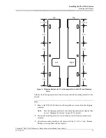
Page 45: ...sories from the shipping container Note Save the shipping container for any future requirements to ship the chas sis see Shipping the System on page 55 for details 2 Position the mounting brackets in the desired position flush mounted or mid mounted 3 Fasten the mounting brackets to the chassis with the 12 8 32 x 1 4 in flathead Phillips screws supplied with the brackets Figure 6 Mounting Brackets...

Page 46: ...sis to the equipment rack before inserting the modules It is recommended that two installers be used in the initial installation as required Perform the following procedure to mount the chassis to an equipment rack Begin Mounting the Chassis 1 Place the chassis top side up in the desired position in the equipment rack The chassis is 40 0 cm 15 75 in high or 9 rack units RUs 1 RU 1 75 in 2 Align th...

Page 47: ...eway Installation Guide Issue 4 Installing the PSAX 2300 System Installing the Hardware Figure 7 Securing the Chassis to a 23 in Equipment Rack Flush Mount Position Figure 8 Securing the Chassis to a 23 in Equipment Rack Mid Mount Position PSAX 2300 PSAX 2300 ...

Page 48: ...ch could affect voice quality Performing the following procedure to connect the facility ground wire to the chassis Begin Connecting the Ground Wire 1 Run the ground wire between the facility ground point and the rear of the chassis Note The chassis ground lug is located on the right side of the rear panel and labeled 2 Strip 1 2 in of the insulation from the end of the wire Note If stranded wire ...

Page 49: ...fore you begin the following procedure check with the facility manager to ensure that a power distribution fuse panel has been properly installed in the equipment rack The PSAX 2300 chassis power connections accept 5 3 3 3 mm2 10 12 AWG stranded wire The facility manager must determine the appropriate wire size and type based on facility requirements and telco standards NEC and GR 1089 Note Two se...

Page 50: ...the power distribution fuse panel and the chassis Note The two chassis power connections are located on the rear panel and labeled and RETURN 3 At the chassis if a double insulated cable is used strip the outer insulation 8 10 in back from the end of the cable 4 Strip 1 2 in of the insulation off the end of the wires using wire strippers Note If stranded wire is used twist the wire and solder the ...

Page 51: ... 10 Repeat the previous steps to attach the second power cable to the second terminal block Figure 12 illustrates how the facility power and ground cables are properly attached to the rear of the chassis Secure the cables with tie wraps and run them to either side of the chassis DANGER Verify that the polarity of the power connections match at both ends of the wires 48 V dc to 48 V dc and return t...

Page 52: ...Supply module into one of the large openings at the bottom of the chassis and push it firmly in until it snaps into the chassis backplane as shown in Figure 13 3 Using a flathead screwdriver tighten the two spring loaded captive screws on both sides of the Power Supply module as shown in Figure 14 WARNING The Power Supply module must be securely inserted into the backplane connec tor before the tw...

Page 53: ...em gently not forcefully Exces sive force may cause the modules to be seated improperly in the chassis and result in possible damage to the module or the chassis Install or remove modules one at a time Doing this aids in preventing the PSAX system from indicating any erroneous failure messages and allows the PSAX system time to reinitialize and display the accurate configuration of the module that...

Page 54: ...s screwdriver as shown in Figure 15 7 Tighten the captive screw at the upper edge of the module using a Phillips screw driver as shown in Figure 15 WARNING Both screws must be properly secured to ensure proper module and backplane connection and operation 8 Repeat the previous steps to install the second redundant Stratum 3 4 module into slot B 9 After you complete this procedure continue with the...

Page 55: ... the PSAX system from indicating any erroneous failure messages and allows the PSAX system time to reinitialize and display the accurate configuration of the module that is inserted WARNING When installing the modules into the chassis pressing directly on the ejector of the module may cause the modules to be seated at an angle If the modules are seated at an angle there is added pressure on the pl...

Page 56: ...ies this product before proceeding WARNING When inserting modules into the chassis slide them gently not forcefully Exces sive force may cause the modules to be seated improperly in the chassis and result in possible damage to the module or the chassis Install or remove modules one at a time Doing this aids in preventing the PSAX system from indicating any erroneous failure messages and allows the...

Page 57: ...the screwdriver slot of the locking tab and slide the locking tab down into the locking tab slot see Figure 17 6 After you complete this procedure continue with this section End Making Common Equipment Connections After installing the common equipment modules Stratum 3 4 CPUn and Alarm modules use the following procedures to connect the console workstation and exter nal timing source to the chassi...

Page 58: ...tion Begin Connecting the Chassis to the Console Workstation 1 Attach the RJ 12 to DB9 or RJ 12 to DB25 adapter to the serial port on the lap top or workstation 2 Connect the serial interface cable between the connection labeled CONSOLE on the active CPUn module ACTIVE LED illuminated and the workstation Note A second console cable and workstation can be connected to the standby module ACTIVE LED ...

Page 59: ...odem The following procedure requires the following items to dial in to the PSAX system External 9600 baud dialup modem Phone line and telephone number Computer or laptop with a dialup modem and terminal emulator package at the local site Workstation with a dialup modem and terminal emulator package at the remote site Note To perform this operation the system must have power applied to it and be o...

Page 60: ...lan Note For a list of clock inputs that the PSAX 2300 Stratum 3 4 module can accept see Stratum 3 4 Module Specifications on page 10 DANGER The Stratum module external clock input that exits the building premises must be connected to any nationally recognized testing laboratory NRTL listed tele communications protection device that provides primary and secondary protec tion 2 Run the cable betwee...

Page 61: ...tatus control cable between the appropriate CO remote control access panel remote sensor panel and the STATUS CONTROL connector on the module 5 After you complete this procedure continue with Applying Power to the Sys tem to apply power End Applying Power to the System At this point in the installation you can proceed with this section to make sure the chassis and common equipment are functioning ...

Page 62: ...te and Please wait while the system initializes is displayed When the initialization is complete Press RETURN to log in is displayed Note If your PSAX 2300 system does not start properly see Technical Sup port on page 3 5 After you complete this procedure continue with the next section End Checking the Status LED Indicators After supplying power to your PSAX 2300 system verify the status of the LE...

Page 63: ...12 Stratum 3 4 Module Status Indicators When the Stratum 3 4 module is installed verify the status of the LED indicators as described in Table 13 Figure 18 Status Indicators on the 48 V dc Power Supply Module FAIL non redundant ACTIVE 10 A 10 A LED Indicators Fuses Power Supply 48 V 125 Amps 23N11 Table 12 Power Supply Module Status LED Indicators Indicators Color Description FAIL Red Indicates th...

Page 64: ... LineTiming UNLOCKED Yellow Indicates the Stratum 3 4 is not locked to a reference signal LAMP TEST Tests the operational status of the LEDs LAMP TEST UNLOCKED ACTIVE FAIL STRATUM 3 4 CLK LOS Table 14 CPU4 Module Status LED Indicators Module Indicator Color Description FAIL Red Indicates that the module is in the process of booting illumi nates for several seconds or is not functioning properly il...

Page 65: ...ng installation and removal of a PSAX module WARNING When inserting modules into the chassis slide them gently not forcefully Exces sive force may cause the modules to be seated improperly in the chassis and result in possible damage to the module or the chassis Install or remove modules one at a time Doing this aids in preventing the PSAX system from indicating any erroneous failure messages and ...

Page 66: ... of the module faceplate and slide the module into an available slot as instructed in the appropriate chassis user guide Be sure to position the module with the ejector handle near the top edge of the chassis opening 3 Press on both ends of the module faceplate until the module is seated into the backplane connector 4 Engage the ejector to lock the module in place Verify that the module is secure ...

Page 67: ...onnect the network cabling to the connectors on the I O modules as required WARNING To prevent damage to an optical interface clean all fiber optic cable connections with the appropriate cleaning system before connecting the cable to any module with fiber optic connections 4 After you complete this procedure continue with the next section End Configuring and Testing the System At this point the ph...

Page 68: ...System Configuring and Testing the System 44 255 700 161 PacketStar PSAX 2300 Multiservice Media Gateway Installation Guide Issue 4 This completes the installation procedures for the PSAX 2300 Multiservice Media Gateway system ...

Page 69: ... PSAX 2300 chassis nor the Power Supply module has a power switch The power to the chassis is controlled through the power distribu tion fuse panel at the installation site Begin Shutting Down the System 1 From the console interface or the EMS PSAX menu back up and save system configuration files and log off Refer to the PacketStar PSAX Multiservice Media Gateway User Guide to backup or save confi...

Page 70: ... and maintain proper air flow through the chassis Removing a DC Power Supply Module Perform the following procedure to remove the 48 V dc Power Supply module from the chassis Begin Read the PacketStar PSAX Multiservice Media Gateway Safety Guidelines which accompanies this product before proceeding WARNING Remove only one Power Supply module at a time in a live network 1 Using a flathead screwdriv...

Page 71: ...ed according to all laws and regulations in your specific geographic region End Removing an I O or a CPUn Module Perform the following procedure to remove the module Perform the following proce dure to remove an I O a CPU2 or a CPU4 module To remove server modules see Removing a Server Module on page 49 Read the PacketStar PSAX Multiservice Media Gateway Safety Guidelines which accompanies this pr...

Page 72: ...handle until the module is released from the mid plane backplane 4 Insert a flathead screwdriver into the screwdriver slot of the locking tab and slide the locking tab up and out of the locking tab slot see Figure 21 5 Pull backward on the ejector handle until the module is released from the back plane midplane 6 Remove the module from the chassis Figure 20 Locking a Module in the PSAX 1000 Chassi...

Page 73: ...r specific geographic region End Removing a Server Module Perform the following procedure to remove a server module To remove an I O or a CPU4 or CPU2 module see Removing an I O or a CPUn Module on page 47 Read the PacketStar PSAX Multiservice Media Gateway Safety Guidelines which accompanies this product before proceeding WARNING Be sure to use the ejector handles during installation and removal ...

Page 74: ...Alarm module Read the PacketStar PSAX Multiservice Media Gateway Safety Guidelines which accompanies this product before proceeding Begin 1 Disconnect the cables from the two connectors 2 For modules that have the locking tab at the bottom of the faceplate insert a flat head screwdriver into the screwdriver slot and slide the locking tab up and out of the locking tab slot see Figure 23 3 Pull back...

Page 75: ...ity of the chassis The following procedures describe how to install and remove blank faceplates with the PSAX 2300 chassis Installing Blank I O CPU Faceplates Perform the following procedure to install the Blank I O CPU faceplates in the PSAX 2300 chassis Begin Installing the Blank I O CPU Faceplates 1 Remove the faceplate from the box and protective packing material Save these materials for futur...

Page 76: ...emoving Blank I O CPU Faceplates Perform the following procedure to remove the Blank I O CPU faceplates from the chassis Begin Removing the Blank I O CPU Faceplates 1 Loosen the captive screw in the ejector handle with a Phillips screwdriver 2 Pull on the ejector handle and remove the faceplate from the chassis 3 Put the blank faceplate in an appropriate storage bag Figure 24 Inserting Blank Facep...

Page 77: ...n it Then an inspection and replacement cycle can be established Depending on air quality more frequent inspections may be required Use only air filters supplied by Alcatel Lucent in the PSAX 2300 chassis Ordering information can be found in Appendix B Refer to Warranty Information on page xiii for additional information concerning proper use of the air filter WARNING Inspect the air filter for du...

Page 78: ...ording to all laws and regulations in your specific geographic region End Replacing the Power Supply Module Fuses Each Power Supply module contains two fuses When a fuse fails a red white flag appears in the fuse lens and if the Alarm module is installed an audible alarm can be sounded Also the red FAIL LED indicator illuminates when the Power Supply mod ule fails Note The fuses can be replaced wh...

Page 79: ...ment when shipping the PSAX 2300 chassis in either situation Shipping a Standalone System Perform the following procedure to prepare the PSAX 2300 system for shipment as a standalone unit WARNING Do not ship the standalone chassis with the modules installed Lateral forces imposed on the chassis during shipping could damage the midplane components and the installed modules Begin Shipping the System...

Page 80: ...ate packing material to support the equipment 6 Secure the boxes with heavy duty packing tape CAUTION Ultimate disposal of this product should be handled according to all laws and regulations in your specific geographic region End Shipping a Rack Mounted System The PSAX 2300 system can be shipped as part of a rack mounted system with or without the modules installed as long as appropriate structur...

Page 81: ...nd console cable adapters are supplied with the chassis to connect the system to a workstation The console cable adapters are described in Console Cable Adapters on page 59 ETHERNET1 and ETHERNET2 Connector The CPU4 module faceplate also provides two 10 100BASE T Ethernet interfaces using two RJ 45 connectors Figure 27 shows the pin locations for both of the Ethernet connectors on the faceplate of...

Page 82: ...tation The console cable adapters are described in Console Cable Adapters on page 59 ETHERNET Connector The CPU2 module faceplate also provides a 10BASE T Ethernet interface using an RJ 45 connector Figure 28 shows the pin locations for the ETHERNET connector on the faceplate of the module Table 17 CPU4 Module ETHERNET1 and ETHERNET2 Connector Pin Assignments Pin Description 1 TD CPU4 transmit 2 T...

Page 83: ... If you are using the console cable supplied with the chassis to connect to the serial port of a personal computer PC or workstation use either an RJ 12 to DB9 adapter or an RJ 12 to DB25 adapter both supplied with the chassis Table 20 describes the pin assignments for RJ 12 to DB9 adapter and Table 21 describes the pin assign ments for RJ 12 to DB25 adapter Table 19 CPU2 Module ETHERNET Connector...

Page 84: ...5 connector on the Stratum 3 4 module Alarm Module Connectors The following connectors ALARM and STATUS CONTROL are provided on the Alarm module model 20N79 for CO alarm sensors and remote controls ALARM Connector Figure 29 illustrates the pin locations of the 26 pin ALARM connector on the Alarm module model 20N79 faceplate Table 22 Stratum 3 4 Module RJ 45 Connector Pin Assignments Pin Descriptio...

Page 85: ...al Alarm COM contact White Brown 13 Audible Critical Alarm NC contact White Violet 1 Audible Critical Alarm NO contact White Tan 4 Audible Major Alarm COM contact White Pink 14 Audible Major Alarm NC contact White Gray 3 Audible Major Alarm NO contact Brown White 6 Audible Minor Alarm COM contact White Orange 15 Audible Minor Alarm NC contact Tan Brown 5 Audible Minor Alarm NO contact Pink White 2...

Page 86: ...ue Color code subject to change without notice COM is common relay contact between NC and NO contacts Audible and visible critical alarm relays are shown normally energized when no alarm is being generated A critical alarm is generated through a command that de energizes the relay or when power is lost NC is normally closed relay contact NO is normally open relay contact Battery Return is used typ...

Page 87: ...l Output 1 NO contact Tan Violet 36 Control Output 2 COM contact Pink Brown 34 Control Output 2 NC contact Gray Tan 35 Control Output 2 NO contact Brown Pink 38 Control Output 3 COM contact Orange Brown 39 Control Output 3 NC contact Brown Yellow 37 Control Output 3 NO contact Brown Orange 42 Control Output 4 COM contact Green Brown 40 Control Output 4 NC contact Yellow Brown 41 Control Output 4 N...

Page 88: ...2 Tan Orange 24 Battery Return Orange Tan 25 Status Input 13 Tan Yellow 26 Battery Return Yellow Tan 27 Status Input 14 Tan Green 28 Battery Return Green Tan 29 Status Input 15 Tan Blue 30 Battery Return Blue Tan Color code subject to change without notice NC is normally closed relay contact NO is normally open relay contact Shown in a normally energized state A control command or loss of power ch...

Page 89: ...larm module If the air filter is dirty replace it with the filter listed in Table 26 Table 25 Orderable Blank Faceplates COMCODE Model Number Chassis Module Name 300338944 23N00 PSAX 2300 PSAX 4500 I O Server CPU Single Slot Blank Faceplate Module 300518487 10N81 PSAX 1000 PSAX 2300 PSAX 4500 I O Server CPU Single Slot Blank Faceplate 300518495 10N82 PSAX 1000 PSAX 2300 PSAX 4500 I O Server CPU Do...

Page 90: ...nch 0 085 in 10 ft One required for 12 Port Medium Density DS1 IMA or Multi service module Two required for 21 Port High Den sity E1 IMA or Multiservice module 300287356 42 02N00037 Shielded RJ 12 to RJ 12 14 ft CPUn Console Cable 300293586 42 02N00038 Shielded RJ 12 to RJ 12 Voice 10 ft 20N32 4 Port Voice 2 Wire Office 20N30 8 Port Voice 2 Wire Sta tion 300164282 42 20N79003 P1 44 pin D type shie...

Page 91: ...013 SubminD to V35F 10ft V 35 DCE 23N07 Quadserial 300468030 42 24N64000 P1 50 pin D type shielded plug to P2 50 pin D type shielded socket and 25 pair shielded cable 10 ft 24N64 12 Port Medium Density DS1 E1 DS0A CES Connects to the STATUS CONTROL socket Connects to the ALARM socket SubminD Subminiture D type 26 position AMPLIMITE 050 Series plug or equivalent DB25F M 25 position AMPLIMITE HDE 20...

Page 92: ...Appendix B Orderable Parts Orderable Cables 68 255 700 161 PacketStar PSAX 2300 Multiservice Media Gateway Installation Guide Issue 4 ...

Page 93: ...er supply specifications see Power Sup ply Module Specifications on page 10 Table 29 Performance and Power Specifications for the PSAX ModulesPerformance and Power Specifications for the PSAX Module Module Total Amount of SDRAM Module Program and Data Space Maximum Input Buffer Output Buffer Chassis Speed Maximum Power Consumption DS1 T1 Interface Modules 20N33 6 Port DS1 IMA IMA DS1 16 MB 8 MB 1 ...

Page 94: ...IMA HD E1 IMA 24 MB 7 MB 4 MB 13 MB 212 992 Low Speed 14 5 W DS3 E3 and STS 1e Interface Modules 23N60 1 Port Channelized DS3 Multiservice CH DS3 24 MB 7 MB 4 MB 13 MB 212 992 Low Speed 13 W 23N68 1 Port DS3 IMA DS3 IMA 24 MB 7 MB 4 MB 13 MB 212 992 Low Speed 13 W 20N03 1 Port Unchannelized DS3 Frame Relay DS3 FR 8 MB 4 MB 1 MB 4 MB 65 536 Low Speed 13 W 20N02 2 Port DS3 ATM DS3 ATM 8 MB 3 MB 1 MB...

Page 95: ... MB 1 048 576 High Speed 10 W 23N12 1 Port Channelized OC 3 STM 1 CES Multimode CH OC 3 STM 1 CES MM 8 MB 8 MB 2 cells port 16 cells port High Speed 17 W 23N13 1 Port Channelized OC 3 STM 1 CES Single mode CH OC 3 STM 1 CES SM 8 MB 8 MB 2 cells port 16 cells port High Speed 17 W 20N72 1 Port OC 3c 1 1 APS Multimode OC 3c MM APS 32 MB 8 MB 12 MB 12 MB 196 608 Low Speed 11 5 W 20N73 1 Port OC 3c 1 1...

Page 96: ...8 W 20N92 1 Port STM 1 1 1 MSP Multimode STM 1 MM MSP 32 MB 8 MB 12 MB 12 MB 196 608 Low Speed 11 5 W 20N93 1 Port STM 1 1 1 MSP Single Mode STM 1 SM MSP 32 MB 8 MB 12 MB 12 MB 196 608 Low Speed 11 5 W 23N72 1 Port OC 12c STM 4c Multimode OC 12c STM 4c MM 72 MB 8 MB SDRAM 1 MB SRAM 32 MB 32 MB 524 288 High Speed 13 W 23N73 1 Port OC 12c STM 4c Single Mode OC 12c STM 4c SM 72 MB 8 MB SDRAM 1 MB SRA...

Page 97: ...Server DSP2E 2 MB SRAM 2 MB N A N A High Speed 13 W 23N25 DSP2F Voice Server DSP2F 2 MB SRAM 2 MB N A N A High Speed 13 W 23N24 DSP2G Voice Server DSP2G 2 MB SRAM 2 MB N A N A High Speed 15 W Other Server Modules 23N41 Enhanced Router ROUTER 512 MB 490 MB N A N A High Speed 18 W 20N41 Route Server ROUTE SERVER 64 MB 8 MB N A N A Low Speed 15 W 23N28 Tones and Announcements Server TAS 1 MB SRAM 512...

Page 98: ...l SDRAM for this module includes 2 MB of SRAM The value 24 MB refers to the maximum data buffer input and output buffers combined The SDRAM listed only takes into account the memory associated with the upper layer processor It does not take into account the fastpath processor firmware or the hardware reassembly buffers Table 30 PSAX I O Module Connectors Module Connector DS1 T1 Interface Modules 2...

Page 99: ...1 APS Single Mode OC 3c SM APS 2 ea SC 1 TX 1 RX 20N92 1 Port STM 1 1 1 MSP Multimode STM 1 MM MSP 2 ea ST 1 TX 1 RX 20N93 1 Port STM 1 1 1 MSP Single Mode STM 1 SM MSP 2 ea SC 1 TX 1 RX 23N12 1 Port Channelized OC 3 STM 1 CES Multimode CH OC 3 STM 1 CES MM 2 ea SC 1 TX 1 RX 23N13 1 Port Channelized OC 3 STM 1 CES Single mode CH OC 3 STM 1 CES SM 2 ea SC 1 TX 1 RX 23N72 1 Port OC 12c STM 4c Multim...

Page 100: ...7 PSAX 12 Port BNC Patch Panel 1 ea 50 pin RJ 48H 12 ea BNC 6 TX 6 RX Serial Interface Modules 20N07 6 Port Multiserial SERIAL 6 ea Micro DB15 23N07 Quadserial QUAD SERIAL 4 ea Micro DB15 Ethernet Interface Modules 20N40 Ethernet ENET 5 ea RJ 45 23N40 4 Port Ethernet ENET 4 ea RJ 45 24N40 2 Port Gigabit Ethernet GIGABIT ENET 4 ea RJ 45 Stratum 3 4 Modules 23N05 PSAX 2300 Stratum 3 4 STRATUM 3 4 1 ...

Page 101: ...M Virtual Interface Bridge CAS Trunkline Circuit Emulation Frame Relay UNI NNI GR 303 HDLC Pass through PRI ISDN Network User Routing Terminal Emulation V5 2 Gigabit Ethernet Bridge Gigabit Ethernet Pseudowire Module DS1 T1 Interface Modules 20N33 6 Port DS1 IMA IMA DS1 X X X X X 20N36 6 Port Enhanced DS1 T1 Multiservice DS1 T1 Enh X X X X X X X X X 23N64 12 Port Medium Density DS1 Multiservice MD...

Page 102: ...Protection X X 23N74 3 Port DS3 E3 ATM DS3 E3 ATM X X X X X 45N74 3 Port DS3 E3 ATM Protection X X X X X 23N02 3 Port Unstructured DS3 E3 CES UNSTR DS3 E3 CES X 45N02 3 Port Unstructured DS3 E3 CES Protection UNSTR DS3 E3 CES X E1 Interface Modules 20N34 6 Port E1 IMA IMA E1 X X X X X 20N56 6 Port Enhanced E1 Multiservice E1 Enh X X X X X X X X X Table 31 Interface Type by I O Module Type Continue...

Page 103: ...ber Optic Interface Modules 23N12 1 Port Channelized OC 3 STM 1 CES Multimode CH OC 3 STM 1 CES MM X X 23N13 1 Port Channelized OC 3 STM 1 CES Single mode CH OC 3 STM 1 CES SM X X X 23N76 1 Port Channelized OC 3 STM 1 Unstructured CES ATM Single Mode CH OC 3 STM 1 UNSTR ATM SM X X X X X 23N75 1 Port Channelized OC 3 STM 1 Unstructured CES ATM Multimode CH OC 3 STM 1 UNSTR ATM MM X X X X X Table 31...

Page 104: ...S X X X X X 20N92 1 Port STM 1 1 1 MSP Multimode STM 1 MM MSP X X X X X 20N93 1 Port STM 1 1 1 MSP Single Mode STM 1 SM MSP X X X X X 23N72 1 Port OC 12c STM 4c Multimode OC 12c STM 4c MM X X X X X 23N73 1 Port OC 12c STM 4c Single Mode OC 12c STM 4c SM X X X X X 24N74 2 Port OC 3c STM 1 Enhanced ATM Multimode OC 3c STM 1 MM Enh ATM X X X X Table 31 Interface Type by I O Module Type Continued Inte...

Page 105: ...ircuit Emulation in DS1 E1 and DS0A modes The module supports GR 303 in DS1 mode only The module supports PRI ISDN in DS1 and E1 modes only The module supports ATM services in the STM ATM mode only The module supports CE in the OC3 UCE mode only European modules do not support this interface with the 8 Port Voice 2 Wire Station module or the 4 Port Voice 2 Wire Office module Table 31 Interface Typ...

Page 106: ...Appendix C Module Information Interface Types by I O Module 82 255 700 161 PacketStar PSAX 2300 Multiservice Media Gateway Installation Guide Issue 4 ...

Page 107: ...pin assignments 60 cable requirements 15 installing 32 removing 50 setting locking tab 33 specifications 12 STATUS CONTROL connector pin assignments 62 Applying Power to the System 37 Attaching Mounting Brackets flush mounted 18 mid mounted 18 Audience for this Guide 1 Available Interface Types by I O module 77 B Before You Begin Installing the System 17 Blank Faceplates orderable parts 65 removin...

Page 108: ...system 41 Checking CPU4 Module Status Indicators starting the system 40 Checking Power Supply Module Status Indicators starting the system 39 Checking Stratum 3 4 Module Status Indicators starting the system 39 Class A Electromagnetic Compatibility EMC Regulatory Statement xxii Clock Input Stratum 3 4 module 11 Clock Synchronization Source Stratum 3 4 module 10 Clothing ESD precautions xxiv CO Ala...

Page 109: ...s indicators 40 installing 31 pin assignments CONSOLE connector 57 ETHERNET1 2 connector 57 removing 47 setting the locking tab 31 specifications 11 D Dimensions chassis 9 CPU2 module 11 CPU4 module 11 power supply module 10 Stratum 3 4 module 10 E Electrostatic Discharge ESD Precautions xxii Equipment Grounding Requirements 14 Equipment Racks mounting hole spacing 20 Ethernet Cable cabling requir...

Page 110: ...eplate Module COMCODE 65 Icons and Symbols 2 Input Power Specifications 10 Installing the Hardware Alarm module 32 attaching the mounting brackets 18 grounding the chassis 24 installing the CPU2 module 31 installing the CPU4 module 31 installing the Stratum 3 4 module 29 mounting the chassis 22 Power Supply module 28 Installing the System 17 attaching the mounting brackets 18 configuring and testi...

Page 111: ...LED Power Supply module 39 Notices xiii O Operating Temperature system 9 Orderable Parts air filter 65 blank faceplates 65 cables 66 fuses 66 Other Publications 2 P Pin Assignments ALARM connector 60 CONSOLE connector CPU2 module 58 CPU4 module 57 ETHERNET connector CPU2 module 58 ETHERNET1 2 connector CPU4 module 57 Stratum 3 4 module external clock connector 60 Power Supply Module cabling requir...

Page 112: ...odules 47 Removing the Power Supply Module 46 Removing the Server Modules 49 Removing the Stratum 3 4 Module 46 Replacement Air Filter 65 Replacement Fuses 66 Replacing Power Supply Fuses 54 Replacing the Air Filter 53 Restricted Access Facilities ventilation requirements 13 RJ 12 to DB25 Adapter pin assignments 59 RJ 12 to DB9 Adapter pin assignments 59 S Safety Compliance xv Safety Information x...

Page 113: ... input 11 installing module 29 removing module 46 specifications 10 status indicators 39 Supplied Accessories 8 System Hardware Components getting started 7 System Startup Response applying DC power 38 T Technical Support 3 Text Types Used in This Document 2 Tools and Materials Needed 15 Trademark Information xiii U UNLOCKED LED Stratum 3 4 module 40 Unrestricted Access Facilities ventilation requ...

Page 114: ...Index W 90 255 700 161 PacketStar PSAX 2300 Multiservice Media Gateway Installation Guide Issue 4 ...

Page 115: ...ed at the end of this checklist for additional notes Checklists Checklist 1 Before Starting the Installation Procedure Your Notes Comments 1 Open the shipping container Save shipping container and all packing materials 2 Open the supplied accessories and inventory the con tents see Supplied Accessories on page 8 for details If your kit is not complete contact your Alca tel Lucent account manager 3...

Page 116: ...e PSAX 2300 system and your other network equipment see Cabling Requirements on page 14 7 Verify your product hardware configuration with your site equipment configuration plan 8 Verify that you have the appropriate tools to install the PSAX 2300 chassis see Tools and Materials Requirements on page 15 for details You can take additional notes at the end of this section Checklist 1 Before Starting ...

Page 117: ...otes at the end of this section Checklist 2 Installing the Hardware Continued Procedure Your Notes Comments Checklist 3 Making the Common Equipment Connections Procedure Your Notes Comments 1 Run and connect the console workstation cabling serial and or Ethernet for network management sys tem control and configuration see on page 33 for details 2 Run and connect the Stratum 3 4 clock cabling see C...

Page 118: ...es Comments 1 Install and secure the I O and server modules see Installing the I O and the Server Modules on page 41 for details Note Do not take the individual modules out of their ESD packaging until you are actually ready to install them in the chassis 2 Run and connect the input output DS1 E1 DS3 E3 STS 1e OC 3c ATM etc module cabling see Connecting the Network Cabling on page 43 for details Y...

Page 119: ...Checklists Continuing Your Notes and Comments Use the following pages to write down any questions or problems you may have encountered during the installation process of the PSAX 2300 system Use this infor mation if you have to contact Alcatel Lucent Technical Support see Technical Sup port on page 3 for details Step Notes ...

Page 120: ...Installation Checklist Checklists Checklist 6 255 700 161 PacketStar PSAX 2300 Multiservice Media Gateway Installation Guide Issue 4 Step Notes ...

Page 121: ......

Page 122: ...Copyright 2008 Alcatel Lucent All rights reserved Part Number 2300M0A0001C4 ...

Reviews: