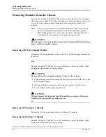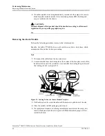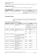
Appendix A Common Equipment Module Connections
Stratum 3–4 Connector
60
255-700-161
PacketStar
®
PSAX 2300 Multiservice Media Gateway Installation Guide
, Issue 4
Stratum 3–4 Connector
The composite clock signal is a balanced signal, which is transmitted over a shielded
twisted pair cable. The cable shield is grounded at the composite clock source.
Table 22 describes the pin assignments for the faceplate RJ-45 connector on the
Stratum 3–4 module.
Alarm Module Connectors
The following connectors (
ALARM
and
STATUS/CONTROL
) are provided on the
Alarm module (model 20N79) for CO alarm, sensors, and remote controls.
ALARM Connector
Figure 29 illustrates the pin locations of the 26-pin
ALARM
connector on the Alarm
module (model 20N79) faceplate.
Table 22. Stratum 3–4 Module RJ-45 Connector Pin Assignments
Pin
Description
1
IN (ring)
2
IN (tip)
3
Not Used
4
Not Used
5
Not Used
6
Frame Ground
7
Not Used
8
Not Used
Figure 29. ALARM Connector Pin Locations on the Alarm Module
9
18
26
1
10
19
Pin 1
Pin 10
Pin 26
Pin 18
Pin 9
Pin 19

