Appendix A Common Equipment Module Connections
Alarm Module Connectors
62
255-700-161
PacketStar
®
PSAX 2300 Multiservice Media Gateway Installation Guide
, Issue 4
STATUS/CONTROL Connector
Figure 31 illustrates the pin locations of the 44-pin
STATUS/CONTROL
connector on
the Alarm module (model 20N79) faceplate.
A shielded 3.7-meter (12-foot) Alcatel-Lucent cable (Part Number 42-20N79003,
COMCODE 300164282) is available with a matching connector on one end and a
25-pair twisted pair pigtail on the other end (see Figure 32).
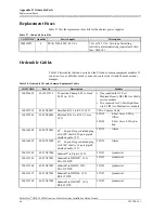
12
Visible Minor Alarm COM contact
Blue/White
18
Visible Minor Alarm NC contact
Green/White
11
Visible Minor Alarm NO contact
White/Blue
*
Color code subject to change without notice.
†
COM is common relay contact between NC and NO contacts.
‡
Audible and visible critical alarm relays are shown normally energized when no alarm is being
generated. A critical alarm is generated through a command that de-energizes the relay or when
power is lost.
§
NC is normally closed relay contact.
¶
NO is normally open relay contact.
**
Battery Return is used typically for -48 V dc operation.
††
Contact closure or input command is sensed by opto-isolator.
Table 23. ALARM Connector Pin Assignments and Cable Pigtail Color Code
(COMCODE 300164290) (Continued)
Connector
Pin
Description
Cable Pigtail Color Code
*
Figure 31. STATUS/CONTROL Connector Pin Locations on the Alarm Module
1
2
3
4
5
6
7
8
9
10
11
12
13
14
15
20
21
22
23
24
25
26
27
28
29
30
16
17
18
19
31
32
33
34
35
36
37
38
39
40
41
42
43
44
ST
A
TUS/CONTR
OL
Pin 1


