background image

DLP-128

Replace Common Control Card (CCC)

5-26

3EM13853AD

Issue 02, July 2006

9

Observe output.

10

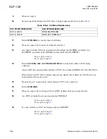
Determine AID of disks for CCC that is being replaced. Refer to table

128-A

.

11

Enter 

RTRV-DISK; 

to check state of all disks.

12

Observe output. Note state of disks A9 and A10.

13

Are disks in both CCCs in valid state? (One Disk A is IS,WRK, one Disk A is 

IS,STBYH, one Disk B is IS,WRK, and one Disk B is IS,STBYH)

If yes, go to step

14

.

If no, go to step

78

.

14

Enter 

ACT-DISK::

AID

::::ACTION=DEACTIVATE; 

to deactivate disk in CCC being 

replaced.

where: AID=Access Identifier of disk on CCC to be replaced (DISK-{A9, A10, B9, B10}).

When disks in CCC that is being replaced are deactivated, disks on CCC that is not 

being replaced become active.

15

Repeat step 

14

 to deactivate other disk on CCC to be replaced.

16

Enter 

RTRV-DISK;

17

Observe output. Note Primary State (PST) of disks that were deactivated.

18

Are PSTs of disks that were deactivated OOS-MA?

If yes, go to step 

19

.

If no, go to step 

78

.

19

Is state of disks in CCC not being replaced IS,WRK?

If yes, go to step

20

.

If no, go to step

78

.

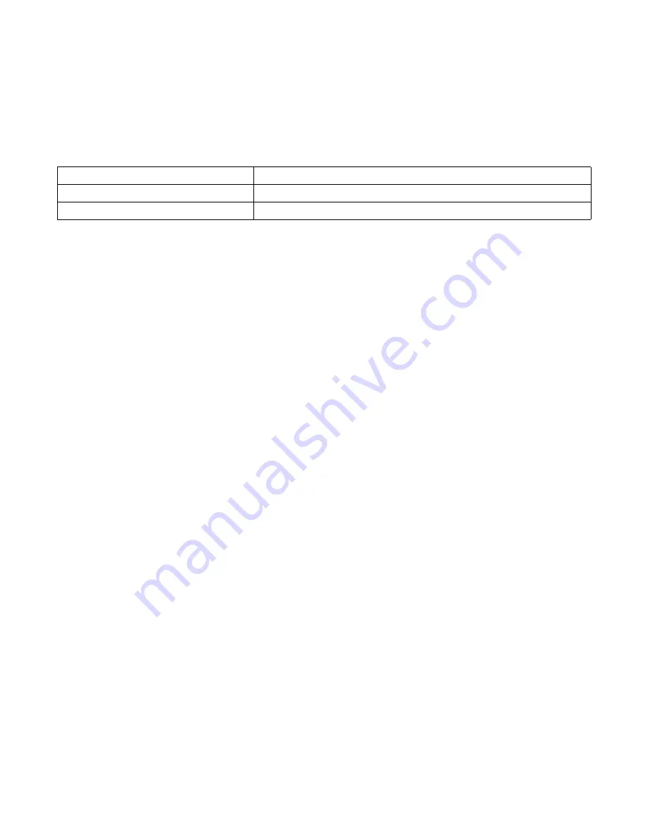
Table 128-A. CCC/Disk Relationship

CCC TO BE REPLACED

AID OF DISK (DISK AID)

CCC in slot 9

DISK-A9, DISK-B9

CCC in slot 10

DISK-A10, DISK-B10

Summary of Contents for 1677 SONET Link

Page 1: ...1677 SONET Link Maintenance and Trouble Clearing PN 3EM13853AD 02 R05 00 Issue 02 July 2006 ...

Page 2: ...dministration Regulations Diversion contrary to U S law is prohibited The export or re export further transfer of such commodities technology software or products made from such technology is prohibited without proper authorization s from the U S Department of Commerce or other appropriate U S government agency s All rights reserved No part of this manual may be reproduced translated stored in a r...

Page 3: ...2 July 2006 Change History 1677 SONET Link Maintenance and Trouble Clearing ISSUE ISSUE DATE SECTION REASON 01 May 2006 Entire manual New software release 02 July 2006 DLP 128 Updated procedure DLP 136 Updated procedure ...

Page 4: ...aser Precautions 1 8 4 ELECTROSTATIC SENSITIVE DEVICES 1 13 Electrostatic Sensitivity 1 13 Handling Circuit Cards 1 14 Repairing Circuit Cards 1 15 5 PRODUCT SUPPORT INFORMATION 1 17 Telephone Support 1 17 Product Documentation and Training 1 17 Technical Assistance Center 1 19 Repair and Return Services 1 20 Spare Parts and Replacement Modules 1 20 Service Center 1 21 Installation and Maintenance...

Page 5: ...CONTBUS 8 Alarm 4 29 TAP 105 CONTBUS MOS 1 or CONTBUS MOS 2 Alarm 4 31 TAP 106 SYNCPRI Alarm 4 33 TAP 107 SYNCSEC Alarm 4 35 TAP 108 FPSWUNLCK Alarm 4 37 TAP 109 SYNCOOS Alarm 4 39 TAP 110 Fan Faults CLFAN CTRLREAD CTRLWRITE INT 4 41 TAP 111 Fuse and Alarm Panel FAP Alarm 4 43 TAP 112 SNTP Alarm 4 45 TAP 113 CONTR Alarm 4 47 TAP 114 CONTR TACC Alarm 4 49 TAP 115 INHPMMON Alarm 4 51 TAP 116 Resolve...

Page 6: ... Alarm 4 77 TAP 128 HWFAIL Alarm 4 81 TAP 129 INHMSG PM Alarm 4 83 TAP 130 INHSWPR Alarm 4 85 TAP 131 INHSWWKG Alarm 4 87 TAP 132 PWR Alarm 4 89 TAP 133 INT 1 Alarm 4 91 TAP 134 INT 19 Alarm 4 93 TAP 135 INT 2 Alarm 4 95 TAP 136 PRCDRERR Alarm 4 97 TAP 137 FACTERM Alarm 4 99 TAP 138 BATTERYLOW Alarm 4 101 TAP 139 CARD 8K DF and CARD INT DF Alarm 4 103 TAP 140 CFGNOSAVE Alarm 4 105 TAP 141 SRFLT SS...

Page 7: ... 5 23 DLP 128 Replace Common Control Card CCC 5 25 DLP 129 Replace DS3 Connector Panel 5 35 DLP 130 Replace 12 Port DS3 Card 5 39 DLP 131 Replace EDFA Card 5 43 DLP 132 Replace Fan Tray Assembly 15 RU Shelf 5 49 DLP 133 Remove Install Filler Panel 5 53 DLP 134 Install Node Protection Shield Kit Replace Node Protection Shield 5 55 DLP 135 Replace OC n Line Card 5 61 DLP 136 Replace STS Switch Card ...

Page 8: ...Issue 02 July 2006 Table of Contents v DLP 145 Fan Tray Assembly Replacement 18 RU Shelf 5 95 DLP 146 Replace ECC 5 97 DLP 147 Replace DS3 Card with ECC Module 5 101 DLP 148 Replace ECC Module with DS3 Card 5 105 ...

Page 9: ...3EM13853AD Issue 02 July 2006 Table of Contents vi ...

Page 10: ...EM07060AAAA 5 7 Figure 101 1 Remove Replace Trim Panel 5 10 Figure 101 2 Connect ESD Wrist Strap to Grounding Jack 5 11 Figure 101 3 Remove or Install EMI Shield 5 11 Figure 101 4 Flash Disk Ejector 5 12 Figure 101 5 Move Switch to Right Type A Lever 5 13 Figure 101 6 Disengage Interlock Lever and Switch Type B Lever 5 13 Figure 101 7 Lift Up Top and Bottom Ejectors 5 14 Figure 101 8 Captive Thumb...

Page 11: ...r Install Fan Tray Assembly 5 51 Figure 133 1 Half High and Full High Filler Panels 5 54 Figure 134 1 Mounting Holes 19 inch ANSI EIA 310D or IEC Equipment Rack 5 57 Figure 134 2 Mounting Holes 19 inch One inch On Center Rack 5 58 Figure 134 3 Mounting Holes 23 inch Racks 5 58 Figure 134 4 Remove or Install Shield 5 59 Figure 138 2 Remove Install LH Three Card Slot Adapter 5 82 Figure 138 1 Remove...

Page 12: ...res 3 1 Table 124 A Purge Level Options 4 70 Table 127 A Protect and Working Transmux Card Slots 4 77 Table 128 A CCC Disk Relationship 5 26 Table 130 A Slot Definitions for ECC and DS3 Card Protection Groups 5 39 Table 137 A TC Disk Relationship 5 72 Table 141 A Protect and Working VT Card Slots 5 85 Table 144 A Protect and Working Transmux Card Slots 5 91 Table 146 A Slot Definitions for ECC and...

Page 13: ...3EM13853AD Issue 02 July 2006 List of Tables x ...

Page 14: ...arted at step 1 and steps must be performed in the order given Failure to do so may cause unforeseen hazardous conditions Writing Conventions 1 2 Boldface characters indicate commands or parameters the user must enter or keys the user must press Enter input parameters exactly as shown in the examples Admonishments 1 3 To avoid hazardous conditions observe the following admonishments DANGER Possibi...

Page 15: ...677 SONET Link Address and Location Guide PN 3EM13854AB Document Types 1 5 The documentation contains all instructions needed to perform a task This manual consists of the following types of documents Task Index List IXL Routine Task List RTL Trouble Analysis Procedure TAP Detailed Level Procedure DLP Task Index List IXL 1 6 IXLs group procedures by function Each IXL lists procedures alphabeticall...

Page 16: ... system Trouble clearing may be done to answer a customer complaint or to respond to an office alarm a trouble report or an abnormal display Steps can refer to other procedures Detailed Level Procedure DLP 1 9 DLPs contain detailed steps and supporting information required to complete tasks When a DLP is referenced from another part of the manual perform the DLP then return to the point where the ...

Page 17: ...3EM13853AD Issue 02 July 2006 Introduction 1 4 ...

Page 18: ... equipment These messages and lights are the primary trouble analysis tools for fault isolation 2 3 The instruction contact next level of technical support for assistance appears throughout this manual The intent of this statement is to trigger escalation of problems that are beyond the scope of this Task Oriented Practice TOP to a higher level of expertise Users who have local interim levels and ...

Page 19: ...DLPs To avoid unnecessary service interruption exercise care when removing circuit cards performing commands and doing other maintenance tasks Always follow electrostatic sensitive device procedures when handling circuit cards TL1 commands can be entered directly or in Menu mode as desired After circuit card replacement alarms can take up to 120 seconds to clear Allow time for the alarm to clear b...

Page 20: ...r other rigid structure before mounting the Alcatel 1677 SONET Link in it For approved methods of securing the equipment rack read the equipment rack installation instructions or contact the equipment rack manufacturer Electrical Precautions 3 2 Take appropriate safety precautions when performing procedures on electrical equipment Hazardous electrical potentials are present when system power is on...

Page 21: ...ury or equipment damage Only Alcatel qualified personnel should connect the dc power to the Alcatel 1677 SONET Link To prevent serious injury or equipment damage make sure the power source cables are de energized before you handle or connect them to the node Laser Precautions 3 4 Verify that laser labels on equipment state that the system conforms to all applicable standards of 21 CFR 1040 10 See ...

Page 22: ...iation hazard to the eyes DANGER Possibility of personal injury This system normally operates as a Class I Laser Product no hazard However during servicing operations when optical connectors are being connected disconnected or handled without dust covers it is possible to be exposed to Class IIIb laser radiation which can cause eye damage DANGER Possibility of personal injury Everyone within a 10 ...

Page 23: ...bject to the following two conditions 1 this devicemay not cause harmful interference and 2 This device must accpet any interference received including interference that may cause undesired operation This equipment is for restricted access installation only Class 1 laser product Complies with 21CF R 1040 10 and 1040 11 Label P N 104731 B Rev 01 ALCATEL USA 19 Alpha Rd Chelmsford MA 01824 Made in U...

Page 24: ... label Laser warning label Revision label RYIOP91202 REV 88 RYIOP98420 RYIOP98420 OK RYIOP98420 RYIOP98205 PGIOP98205 Date of Manufacture label DANGER yuuy ozozozp kjjglgl oipi yuuy ozozozp kjjglgl oipi yuuy ozozozp kjjglgl Danger label DANGER yuuy ozozozp kjjglgl oipi yuuy ozozozp kjjglgl oipi yuuy ozozozp kjjglgl Danger label 677 0058 1 032003 ...

Page 25: ...3EM13853AD Issue 02 July 2006 Introduction 1 12 ...

Page 26: ...ossibility of equipment damage Common plastic white foam cellophane and masking adhesive tapes must not come in contact with ESDs or their packaging 4 2 Common plastics synthetic insulating materials clothing and paper or cardboard are the most common sources of static charges 4 3 Observe special precautions when the ESD sign is displayed See figure 4 3 4 4 The following items are examples of ESDs...

Page 27: ...ve or electrostatic dissipative surfaces Wear ground straps wrist PN 055 9357 010 or heel PN 055 9357 020 before and while touching or handling circuit cards containing ESDs Cover surfaces with resistance to ground in excess of 100 megohms such as ordinary tile with properly grounded static dissipative runners or wax surfaces with a static dissipative wax PN 057 4000 006 Store even temporarily pac...

Page 28: ...ging All electrical equipment must be grounded using a 3 wire power cord Clothing must not touch the device under repair ESDs are delivered with protective packing containers or conductive foam The devices should remain in their original containers until needed Containers with ESDs must contact the antistatic work surface and the wrist strap must be connected before parts are removed from packagin...

Page 29: ...3EM13853AD Issue 02 July 2006 Introduction 1 16 ...

Page 30: ...056 is available to all customers to report quality issues related to products or services 5 4 The Quality Hotline is answered 24 hours a day 365 days a year and is available throughout all 50 states and Canada 5 5 To report quality issues call 800 553 4056 An operator will take the information and have an Alcatel Quality Assurance Representative respond during normal business hours 8 00 a m to 5 ...

Page 31: ...etins PIBs Product manual updates Software patch and software load documents Software Update Documents SUDs Technical bulletins Training documents Urgent Product Warnings UPWs Training 5 8 Equipment training is available to all customers Crafts and maintenance personnel who are trained by Alcatel s Training department can expect more effective assistance if they need to call the Technical Assistan...

Page 32: ...atch operators Call customer service telephone support and ask for the Lightwave Microwave Operations Support System OSS Digital Loop Carrier LMS or Digital Cross Connect emergency duty engineer 5 13 An emergency is defined as an out of service traffic affecting problem or a nonoperating alarm system on traffic bearing systems 5 14 Nonemergency is defined as installation turn ups application quest...

Page 33: ...sts should be made to the Field Service organization 5 18 On site services are billable to the customer Service rates vary depending on product product age product status and the time at which services are performed Copies of on site service rates are available by request from the Technical Assistance Center Repair and Return Services 5 19 As part of a comprehensive technical support program Alcat...

Page 34: ...ned equipment must have a Return Authorization RA number Obtain an RA number either by calling customer service telephone support or by fax 972 519 4611 5 24 No equipment should be returned without an RA number The following information is required Description and quantity of equipment to be returned Reason for return Order number the equipment was purchased against and approximate date of purchas...

Page 35: ...ent of parts The following information must be furnished with the request for return authorization Purchase order number or requisition number Description and quantity of equipment to be returned Reason for return Modification required Defective equipment to be repaired Warranty status in or out of warranty and warranty date stamped on unit Specific nature of problem Name and telephone number of p...

Page 36: ...rtinent details Mail purchase order if applicable to address shown under Return for Repair Procedure Attention Service Center Installation and Maintenance Services Engineering and Installation Service 5 28 Whether installation for specific equipment or a full turnkey network facility is needed Installation Service can help Alcatel has experience in central office outside plant and customer premise...

Page 37: ... 5 30 Factory trained service technicians are qualified on similar systems before they are allowed to maintain customer equipment They have direct access to additional technical support around the clock and to all necessary tools and test equipment ...

Page 38: ...rmation needed to perform maintenance and trouble clearing on the system Table 100 A Task Index List TYPE OF PROCEDURE INFORMATION REFERENCE Alarm and event condition clearing procedures IXL 101 Support procedures IXL 102 Equipment replacement procedures IXL 103 Supporting information IXL 104 Preventive maintenance procedures RTL 100 Performance monitoring RTL 101 ...

Page 39: ...IXL 100 Task Index List 2 2 3EM13853AD Issue 02 July 2006 ...

Page 40: ...entities are listed by software mnemonic Observe the following definitions Stand alone DS3 DS3 that is not embedded Embedded DS3 DS3 embedded in EC1 OC 3 OC 12 OC 48 or OC 192 EC1 EC1 OC3 OC 3 OC12 OC 12 OC48 OC 48 OC192 OC 192 STS1 STS 1 embedded in EC1 OC 3 OC 12 OC 48 or OC 192 STS3c STS 3c embedded in OC 3 OC 12 OC 48 or OC 192 STS12c STS 12c embedded in OC 12 OC 48 or OC 192 STS48c STS 48c em...

Page 41: ...ication signal STS 1 STS 3c STS 12c STS 48c TAP 100 AIS V VT path alarm indication signal VT1 5 TAP 100 APSB Automatic protection switching byte failure OC 3 OC 12 OC 48 OC 192 TAP 113 APSCDFLTK Default K byte received OC 48 OC 192 TAP 100 APSCIMP Improper K byte received OC 48 OC 192 TAP 100 APSCINCON Inconsistent K byte received OC 48 OC 192 TAP 100 APSCM Automatic protection switching channel m...

Page 42: ...OV BLSR Autodiscovery Topology Error OC 48 OC 192 TAP 100 BOOTROM VER Boot ROM version check skipped due to disk synchronization CCC SSC transient1 No action BP BLSR Protection Switching State is Bidirectional Full Passthrough OC 192 TAP 100 CARD 8K DF Card detects 8k clock loss defect SSC transient1 TAP 139 CARD INT DF Card internal defect is detected on component SSC transient1 TAP 139 CFG RESET...

Page 43: ...e two CCCs MOS TAP 105 CONTBUS MOS 3 Mismatch in number of MOS devices discovered by each CCC MOS transient1 No action CONTR Control processor failure CCC SSC TAP 113 CONTR TACC Test access is inhibited due to control processor module failure SSC TAP 114 CTRLREAD Fan controller read operation failure FANTRAY TAP 110 CTRLWRITE Fan controller write operation failure FANTRAY TAP 110 DISK90 A Drive A ...

Page 44: ...eempted by ring condition OC48 OC192 transient1 No action EXTCMD DEFAULT Command was rejected adjacent node is incapable of signaling OC48 OC192 transient1 No action EXTCMD DUP Command was rejected duplicated command OC48 OC192 transient1 No action EXTCMD EQUAL PRI Command was rejected equal priority to the existing command OC48 OC192 transient1 No action EXTCMD LOWER PRI Command was rejected lowe...

Page 45: ...t remote terminal T3 TAP 100 FEACDS1MLOS Multiple DS1 LOS failure at remote terminal T3 TAP 100 FEACEFAILCOM Common equipment failure at remote terminal T3 TAP 100 FEACEFAILNSA Non service affecting DS3 equipment failure at remote terminal T3 TAP 100 FEACEFAILSA Service affecting DS3 equipment failure at remote terminal T3 TAP 100 FEACISD DS3 ISD failure at remote terminal T3 TAP 100 FEACLOF DS3 L...

Page 46: ...n is suspected CHASSIS transient1 No action FWMISM Firmware mismatch TMUX TAP 127 HLDOVRSYNC Manual or automatic switch to hold over synchronization mode TC TAP 118 HLTHVER Health FPGA version is incompatible with peer card IOC SSC CCC TAP 142 HWFAIL Hardware error is detected on module DS3 ECC EDFA GIGE OC3 OC12 OC48 OC192 TMUX VSC TAP 128 IDROMREADER Physical ID ROM could not be read CCC SSC TC ...

Page 47: ...HASSIS TAP 135 INTERR Internal error has been detected for the module Applies to DS3 ECC EDFA GIGE OC3 OC12 OC48 and OC192 modules IOC transient1 No action IOC 8K DF IOC card detects 8k clock loss defect TMUX VSC transient1 No action IOC 8K DF IOC card detects 8k clock loss defect DS3 EC1 GIGE OC 3 OC 12 OC 48 OC 192 transient1 No action IOC INT DF IOC card internal defect is detected on HYPERMAPP...

Page 48: ...ports TAP 100 LCPSCONFAIL LCP Section DCC connection failure Alarm raised after MAXCONFIG count exhausted OC n ports TAP 100 LCPSDF LCP Section DCC failure Alarm raised after MAXTERM count exhausted or ECHOREPCOUNT exhausted or reception of Code reject OC n ports TAP 100 LDCCDLFL Line DCC data link connection failure After establishing a connection Line DCC communication failed and the problem per...

Page 49: ...r protection is available NSA DSK DLP 128 MANRESET Manual system reset CHASSIS transient1 No action MANWKSWBK Manual switch to working OC3 OC12 OC48 OC192 TAP 100 MANWKSWBK Manual switch to working Applies to UPSR facilities STS 1 STS 3c STS 12c STS 48c No action MANWKSWPR Manual switch to protection OC3 OC12 OC48 OC192 TAP 100 MANWKSWPR Manual switch to protection Applies to UPSR facilities STS 1...

Page 50: ...k transmit reference GIGE TAP 100 OOS Out of Sync GIGE TAP 100 PLM P Payload label mismatch path STS 1 STS 3c STS 12c STS 48c TAP 100 PLM V Payload label mismatch path VT1 TAP 100 PRCDRERR Procedure error Card is inserted in wrong slot TC IOC TAP 136 PROTNA Protection Not Available Applies to UPSR STS1 working facilities STS1 TAP 100 PWR Power failure POWER IOC TAP 132 RAI Remote alarm indication ...

Page 51: ...e server at the specified interval CHASSIS TAP 112 SRFLT CIRRUS Internal subsystem failure Error while accessing the Cirrus PC Card controller TC transient1 No action SRFLT DISK0 Internal subsystem failure Error while accessing lower disk control registers TC transient1 No action SRFLT DISK1 Internal subsystem failure Error while accessing upper disk control registers TC transient1 No action SRFLT...

Page 52: ...quality level has changed TC transient1 No action SYSBOOT Startup configuration database download has completed CHASSIS transient1 No action SYSDBG System is operating in debug mode CHASSIS TAP 122 SYSREADY System is ready to accept TL1 messages CHASSIS No action TEMP Temperature sensor has detected very high temperature CR or marginally high temperature MN CHASSIS TAP 126 TH LBCN HT Laser Bias Cu...

Page 53: ...tion WKSWBK Automatic Protection Switch to Working OC 3 OC 12 OC 48 OC 192 transient1 TAP 100 WKSWBK Automatic Protection Switch to Working Applies to UPSR STS 1 STS 3c STS 12c STS 48c transient1 No action WKSWBK RING A ring switch back to working has completed Applies to BLSR OC 48 OC 192 transient1 No action WKSWPR APS automatic switch from working to protection This condition is a standing cond...

Page 54: ...for a working module Applies to working DS3 ECC TMUX and VSC modules IOC TAP 100 WTR OC n facility in wait to restore state OC 3 OC 12 OC 48 OC 192 TAP 100 WTR STS n facility in wait to restore state STS1 STS3C STS12C STS48C TAP 100 XMTLPBK Active loopback request to the far end T1 T3 TAP 100 1 Transient alarms are issued only once and are not retrievable using RTRV ALM ALL or RTRV COND ALL Alone ...

Page 55: ...IXL 101 Alarm and Event Condition Clearing Procedures 2 18 3EM13853AD Issue 02 July 2006 ...

Page 56: ...n manual Alarm cut off control Operation and Administration manual Change Line Buildout LBO Operation and Administration manual Clean fiber optic connectors DLP 100 Clock reference and operation mode selections Commands and Messages manual Provision equipment Operation and Administration manual Log into system Operation and Administration manual Loopback DS3 EC1 OC 3 OC 12 OC 48 OC 192 STS 1 STS 3...

Page 57: ...IXL 102 Support Procedures 2 20 3EM13853AD Issue 02 July 2006 ...

Page 58: ...7 Common Control Card CCC DLP 128 DS3 Connector Panel DLP 129 DS3 Interface Card DLP 130 Erbium Doped Fiber Amplifier EDFA DLP 131 Fan Tray Assembly 15RU DLP 132 Filler Panels DLP 133 Node Protection Shield DLP 134 OC n Line Card DLP 135 STS Switch Card SSC SWC DCC DLP 136 Timing Card TC DLP 137 Card Slot Adapter DLP 138 VT Switch Card VSC DLP 141 Modular Optical System MOS DLP 143 Transmux Card T...

Page 59: ...IXL 103 Equipment Replacement Procedures 2 22 3EM13853AD Issue 02 July 2006 ...

Page 60: ...TION REFERENCE Alarm condition types Commands and Messages manual Circuit card locator and addressing Address and Location Guide Command structure and response messages Commands and Messages manual Product support information IIntroduction Electrostatic sensitive devices IIntroduction Error codes Commands and Messages manual How to use TOP documentation IIntroduction Laser precautions IIntroductio...

Page 61: ...IXL 104 Supporting Information 2 24 3EM13853AD Issue 02 July 2006 ...

Page 62: ...ns may require maintenance procedures be performed more or less frequently Table 100 A Preventive Maintenance Procedures ACTIVITY FREQUENCY REFERENCE Replace air filters Every 3 months DLP 127 Check air filters Every 2 months DLP 127 Clean equipment Every 2 months DLP 127 Check fan operation Monthly Refer to 1677 SONET Link Product Information PN 3EM13848AD Maintain printer Monthly Refer to manufa...

Page 63: ...RTL 100 Preventive Maintenance Procedures 3 2 3EM13853AD Issue 02 July 2006 ...

Page 64: ...nd Messages manual PN 3EM13852AD STEP PROCEDURE 1 Select action To retrieve PM data go to step 2 To initialize PM registers go to step 5 To retrieve threshold values go to step 7 To set thresholds go to step 10 To retrieve PM mode go to step 12 To set PM mode go to step 15 To retrieve PM reporting schedule go to step 17 To schedule PM reporting go to step 19 To inhibit PM reporting go to step 21 T...

Page 65: ... Facility Type EC1 GIGE OC3 OC12 OC48 OC192 OFA STS1 STS3C STS12C STS48C T1 T3 VT1 AID Access Identifier of the facility MONTYPE Threshold monitored parameter name or is omitted for all thresholds for the facility type MONVAL New value for the register or is omitted to use the default value 0 LOCN Location associated with command NEND or FEND TMPER Accumulation period for the counter either 15 MIN...

Page 66: ...4 A 1 UASL 900 OC12 14 A 1 CV LFE 16383 OC12 14 A 1 ES LFE 900 OC12 14 A 1 SES LFE 900 OC12 14 A 1 UAS LFE 900 OC12 14 A 1 LBCN 95 OC12 14 A 1 OPRN HT 95 OC12 14 A 1 OPRN LT 3 OC12 14 A 1 LSRTEMP 85 OC12 14 A 2 CVS 16383 OC12 14 A 2 ESS 900 OC12 14 A 2 SESS 900 OC12 14 A 2 SEFS S 900 OC12 14 A 2 CVL 16383 OC12 14 A 2 ESL 900 OC12 14 A 2 SESL 900 OC12 14 A 2 UASL 900 OC12 14 A 2 CV LFE 16383 OC12 1...

Page 67: ...ger or DFLT for the standard default for that threshold TMPER Accumulation period for the counter either 15 MIN or 1 DAY For example agent SET TH OC12 OC12 14 A 1 ESL 10 ALCATEL 1677SL 04 02 05 11 53 47 M 0 COMPLD SET TH OC12 11 Go to step 1 Retrieve PM Mode 12 Enter RTRV PMMODE x AID LOCN where x Facility type EC1 GIGE OC3 OC12 OC48 OC192 OFA STS1 STS3C STS12C STS48C T1 T3 VT1 AID Access Identifi...

Page 68: ... 19 Enter SCHED PMREPT ALL REPTINVL REPTSTATM NUMREPT MONTYPE MONLEV TMPER TMOFST or SCHED PMREPT x AID REPTINVL REPTSTATM NUMREPT MONTYPE MONLEV TMPER TMOFST where x ALL or the Facility Type EC1 GIGE OC3 OC12 OC48 OC192 OFA STS1 STS3C STS12C STS48C T1 T3 VT1 AID Access identifier of the facility REPTINVL Reporting interval indicating how often to generate reports 15 MIN 1 DAY or 15 DAY or is omit...

Page 69: ...ffset between reporting diagnostics exercises 20 Go to step 1 Inhibit PM Reporting 21 Enter INH PMREPT COM or INH PMREPT rr AID where x Facility Type EC1 GIGE OC3 OC12 OC48 OC192 OFA STS1 STS3C STS12C STS48C T1 T3 VT1 AID Access Identifier of the facility 22 Go to step 1 Allow PM Reporting 23 Enter ALW PMREPT ALL or ALW PMREPT COM or ALW PMREPT x AID where x Facility Type EC1 GIGE OC3 OC12 OC48 OC...

Page 70: ...nts not listed refer to IXL 101 For ACTLPBK go to step 3 For AIC go to step 6 For AIS go to step 7 For AIS L go to step 8 For AIS P go to step 9 For AIS V go to step 10 For APSB go to step 11 For APSCCDFLTK go to step 26 For APSCIMP go to step 28 For APSCINCON go to step 30 For APSCM go to step 31 For APSCNMIS go to step 54 For BLSRAD AUTO go to step 64 For BLSRAD DUPNODE go to step 65 For BLSRAD ...

Page 71: ...MANWKSWPR go to step 114 For OALCASETEMP go to step 117 For OALKEYLOCK go to step 118 For OALLBC go to step 119 For OALLOPOW go to step 120 For OALPWR go to step 121 For OALRXLOCK go to step 122 For OALTEMP go to step 123 For OALTXLOCK go to step 122 For OOL RXD go to step 124 For OOL RXR go to step 125 For OOL TXR go to step 125 For OOS go to step 126 For PLM P go to step 127 For PLM V go to step...

Page 72: ... step 156 4 Enter RLS LPBK x AID 5 Did output return a COMPLD or DENY If COMPLD go to step 156 If DENY go to step 155 AIC 6 AIC indicates DS3 Application Identification Channel detected Go to step 155 AIS 7 AIS indicates system is detecting incoming Alarm Indication Signal AIS Problem is outside system Go to step 155 AIS L 8 AIS L indicates system is detecting incoming Line Alarm Indication Signal...

Page 73: ...larms If yes clear alarms Go to IXL 101 If no go to step 16 16 Enter RTRV OCn AID for facility in alarm where OCn Optical facility type OC3 OC12 OC48 or OC192 AID Facility Access Identifier 17 Observe output and note primary and secondary states 18 Does the alarmed OC n facility have secondary state of WRK or STBYH If WRK go to step 19 If STBYH go to step 20 19 Enter OPR PROTNSW OCn AID MAN to swi...

Page 74: ...f yes go to step 156 If no go to step 155 APSCDFLTK 26 APSCDFLTK indicates a default K byte received This alarm is transmitted until a valid ring map is created While this alarm is present no BLSR protection is available Refer to the Operation and Administration manual PN 3EM13851AD to provision ring map 27 Go to step 155 APSCIMP 28 APSCIMP indicates the incoming K byte does not match Enter RTRV A...

Page 75: ...tion switching parameters at incorrect end PROTECTED_ID Working OC 48 in 1 1 FFP group working preferred OC 48 in UPSR group or west OC 48 in BLSR PROTECTING_ID Protecting OC 48 in 1 1 FFP group protecting alternate OC 48 in UPSR group or east OC 48 in BLSR Other parameters are optional If a value is not entered for these parameters the system will use the default value Refer to Commands and Messa...

Page 76: ...l facility type OC3 OC12 OC48 or OC192 AID Facility Access Identifier 45 Observe output and note primary and secondary states 46 Does the alarmed OC n facility have secondary state of WRK or STBYH If WRK go to step 47 If STBYH go to step 48 47 Enter OPR PROTNSW OCn AID MAN to switch service away from alarmed facility at far end where OCn Optical facility type OC3 OC12 OC48 or OC192 AID Facility Ac...

Page 77: ...in a BLSR ring Enter RTRV FFP OCn AID where OCn Optical facility type OC 48 or OC 192 AID OC 48 OC 192 access identifier 55 Observe output and note current value of NODEID parameter 56 Enter OPR PROTNSW OCn AID LOP S where OCn Optical facility OC 48 or OC 192 AID East OC n facility access identifier 57 Enter OPR PROTNSW OCn AID LOP S where OCn Optical facility OC 48 or OC 192 AID West OC n facilit...

Page 78: ... Enter RTRV ALM ALL and RTRV COND ALL and observe output 63 Did APSCNMIS condition clear If yes go to step 156 If no go to step 155 BLSRAD AUTO BLSRPROV 64 BLSRAD AUTO indicates autodiscovery auto mode is set on own node but not on neighbor Go to step 155 BLSRAD DUPNODE DUPNODEID 65 BLSRAD DUPNODE indicates a duplicate node ID has been detected Enter RTRV FFP OCn AID where OCn Optical facility typ...

Page 79: ...where OCn Optical facility OC 48 or OC 192 AID West OC n facility access identifier 71 Enter RLS PROTNSW OCn AID where OCn Optical facility OC 48 or OC 192 AID East OC n facility access identifier 72 Enter RTRV FFP OCn AID to verify new node ID value where OCn Optical facility type OC 48 or OC 192 AID OC 48 OC192 access identifier 73 Enter RTRV ALM ALL and RTRV COND ALL and observe output 74 Did B...

Page 80: ...lity Access Identifier or ALL 77 Observe output Note value of AUTOMAP parameter 78 Does AUTOMAP parameter have value of Y or N If Y ring maps are automatically learned and can not be changed manually Go to step 156 If N go to step 79 79 Enter RTRV RINGMAP AID to retrieve the existing BLSR ring maps where AID OC48 or OC192 Access Identifier or ALL Example Output ALCATEL 1677SL 04 05 30 19 26 57 M 0...

Page 81: ...efine the node ID of the BLSR node in the eastward side The last RINGMAP value defines the node ID of the adjacent BLSR node west side 84 Enter RTRV RINGMAP AID to verify the new ring map where AID OC48 or OC192 access identifier or ALL 85 Enter RLS PROTNSW OCn AID where OCn Optical facility OC 48 or OC 192 AID West OC n facility access identifier 86 Enter RLS PROTNSW OCn AID where OCn Optical fac...

Page 82: ...re on one of the following ports OC 3 OC 12 OC 48 or OC 192 This failure is applicable to 1 1 bidirectional FFP provisioned facilities It applies to the protection OC n facility Check far end OC 3 OC 12 OC 48 and OC 192 provisioning Correct provisioning if necessary Refer to 1677 SONET Link Operation and Administration manual PN 3EM13851AD Then go to step 156 FRCDWKSWBK FRCDWKSWPR or FRCDWKSWPR RI...

Page 83: ...REPT x AID where x facility type ALL COM EC1 GIGE OC3 OC12 OC48 OC192 OFA STS1 STS3C STS12C STS48C T1 T3 VT1 AID Facility Access Identifier 98 Go to step 156 IPCPLCONFAIL or IPCPLDCF 99 IPCPLCONFAIL indicates line IPCP DCC connection failure IPCPLDCF indicates IPCP Line DCC connection failure and is raised after MAXTERM count exhausted or reception of code reject Go to step 155 IPCPSCONFAIL or IPC...

Page 84: ...ction failure These alarms are raised after MAXCONFIG count is exhausted Go to step 155 LCPLDF or LCPSDF 104 LCPLDF indicates Line DCC failure LCPSDF indicates LCP Section DCC failure These alarms are raised after MAXTERM count is exhausted ECHOREPCOUNT is exhausted or reception of code reject LOCC 105 LOCC indicates Loss of Client Character Synchronization on a GIGE facility Go to step 155 LOCKOU...

Page 85: ...tside system Go to step 155 LOL 111 LOL indicates Gigabit Ethernet Loss of Link Go to step 155 LOP P or LOP V 112 LOP P indicates system is detecting Loss of Pointer Path LOP P on one of the following incoming signals STS 1 STS 3c STS 12c or STS 48c LOP V indicates system is detecting Loss of Pointer VT Path LOP V on an incoming VT1 signal Check provisioning Correct provisioning if required Refer ...

Page 86: ...LS PROTNSW OCn AID where OCn Facility type OC3 OC12 OC48 OC192 AID Facility Access Identifier 116 Did output return a COMPLD or DENY If COMPLD go to step 156 If DENY go to step 155 OALCASETEMP 117 OALCASETEMP indicates optical case temperature on an OFA facility Go to step 155 OALKEYLOCK 118 OALKEYLOCK indicates EDFA key lock on an OFA facility Go to step 155 OALLBC 119 OALLBC indicates excessive ...

Page 87: ...OFA OC 48 or OC 192 facility Go to step 155 OOL RXD 124 OOL RXD indicates Out of Lock receive data on GIGE facility Go to step 155 OOL RXR or OOL TXR 125 OOL RXR indicates Out of Lock receive reference for GIGE facility OOL TXR indicates Out of Lock transmit reference for GIGE facility Go to step 155 OOS 126 OOS indicates GIGE facility is out of sync Go to step 155 PLM P 127 PLM P indicates payloa...

Page 88: ...with protection facility Refer to 1677 SONET Link Maintenance and Trouble Clearing manual PN 3EM13853AD 133 Did PROTNA alarm clear If yes go to step 156 If no go to step 155 RAI 134 RAI indicates Remote Alarm Indication RAI detected for a stand alone or embedded DS3 facility Go to step 155 RFI L RFI P or RFI V 135 RFI L indicates a Line Remote Failure Indication for an EC1 OC 3 OC 12 OC 48 or OC 1...

Page 89: ... OC 3 OC 12 OC 48 or OC 192 facilities Go to step 155 TH LBCN HT 140 TH LBCN HT indicates laser bias current upper threshold crossed for OFA OC 48 or OC 192 facilities Enter RTRV ALM ALL 141 Examine output and note AID of facility in alarm to determine which card is generating Laser Bias Current event 142 Replace IOC card To replace an OC n card refer to DLP 135 To replace an EDFA card refer to DL...

Page 90: ...ear end and far end NE Correct provisioning if necessary Refer to 1677 SONET Link Operation and Administration manual PN 3EM13851AD Go to step 156 UNEQ P or UNEQ V 149 UNEQ P indicates unequipped path for STS 1 STS 3C STS 12C or STS 48C facility UNEQ V indicates unequipped VT1 Check provisioning of supporting equipment Correct provisioning if necessary Refer to 1677 SONET Link Operation and Admini...

Page 91: ...LPBKTYPE where x Facility type T1 or T3 AID Facility Access Identifier Other parameters are optional If a value is not entered for these parameters the system will use the default value Refer to Commands and Messages manual PN 3EM13852AD for details on parameter values 154 Did output return COMPLD or DENY If COMPLD go to step 156 If DENY go to step 155 155 Contact next level of technical support f...

Page 92: ...nstructions to clear a BKUPMEMP or BKUPMEMS alarm GENERAL BKUPMEMP indicates the redundant disk is not available This applies to the logical disk BKUPMEMS indicates the redundant disk is not available This applies to the physical disk STEP PROCEDURE 1 Contact next level of technical support for assistance 2 STOP This procedure is complete ...

Page 93: ...TAP 101 BKUPMEMP or BKUPMEMS Alarm 4 24 3EM13853AD Issue 02 July 2006 ...

Page 94: ...POSE This procedure provides instruction to clear a CFGFLT alarm against a CCC or SSC GENERAL CFGFLT indicates configuration database download failure for the processor module STEP PROCEDURE 1 Contact next level of technical support for assistance 2 STOP This procedure is complete ...

Page 95: ...TAP 102 CFGFLT Alarm 4 26 3EM13853AD Issue 02 July 2006 ...

Page 96: ...ar an IOC INT DF against a TMUX GENERAL IOC INT DF indicates IOC card internal defect is detected on HYPERMAPPER component For information on TL1 command syntax refer to the 1677 SONET Link Commands and Messages manual PN 3EM13852AD STEP PROCEDURE 1 Contact next level of technical support for assistance 2 STOP This procedure is complete ...

Page 97: ...TAP 103 IOC INT DF Alarm 4 28 3EM13853AD Issue 02 July 2006 ...

Page 98: ...tructions to clear a CONTBUS 7 or CONTBUS 8 alarm against the CHASSIS GENERAL CONTBUS 7 indicates the system is unable to select a valid message bus A arbiter CONTBUS 8 indicates the system is unable to select a valid message bus B arbiter STEP PROCEDURE 1 Contact next level of technical support for assistance 2 STOP This procedure is complete ...

Page 99: ...TAP 104 CONTBUS 7 or CONTBUS 8 Alarm 4 30 3EM13853AD Issue 02 July 2006 ...

Page 100: ...S MOS 1 or CONTBUS MOS 2 alarm against the Modular Optical System MOS GENERAL CONTBUS MOS 1 indicates hardware error is detected when attempting to enumerate MOS devices after MOS discovery CONTBUS MOS 2 indicates MOS devices are seen by only one of the two CCCs after MOS discovery STEP PROCEDURE 1 Contact next level of technical support for assistance 2 STOP This procedure is complete ...

Page 101: ...TAP 105 CONTBUS MOS 1 or CONTBUS MOS 2 Alarm 4 32 3EM13853AD Issue 02 July 2006 ...

Page 102: ...d into the alarmed Network Element NE using a telnet session to port 3083 For information on TL1 command syntax refer to the 1677 SONET Link Commands and Messages manual PN 3EM13852AD STEP PROCEDURE 1 Enter RTRV SYNCN 2 Observe output Note primary reference and secondary reference 3 Enter RTRV SYNCN SRC to verify timing source on indicated card 4 Observe output Note any defects 5 Contact next leve...

Page 103: ...02 July 2006 Figure 106 1 Locate BITS Connections on TC TIMING EXT STATUS BITS GND RING TIP GND RING TIP GND RING TIP GND RING TIP A B TIMING I N O U T I N O U T E T H E R N E T C O N S O L E BITS A BITS B WIRE WRAP CONNECTIONS 677 0103 1 090804 ...

Page 104: ...mes the user is logged into the alarmed Network Element NE using a telnet session to port 3083 For information on TL1 command syntax refer to the 1677 SONET Link Commands and Messages manual PN 3EM13852AD STEP PROCEDURE 1 Enter RTRV SYNCN 2 Observe output Note primary reference and secondary reference 3 Enter RTRV SYNCN SRC to verify timing source on indicated card 4 Observe output Note any defect...

Page 105: ...TAP 107 SYNCSEC Alarm 4 36 3EM13853AD Issue 02 July 2006 ...

Page 106: ...refer to the 1677 SONET Link Commands and Messages manual PN 3EM13852AD STEP PROCEDURE 1 Enter RTRV ALM ALL and RTRV COND ALL to retrieve all alarms and conditions 2 Observe output Note AID of module in alarm 3 Locate module with FPSWUNLCK alarm and fully engage interlock switch 4 Enter RTRV ALM ALL and RTRV COND ALL 5 Did FPSWUNLCK alarm clear If yes go to step 7 If no go to step 6 6 Contact next...

Page 107: ...TAP 108 FPSWUNLCK Alarm 4 38 3EM13853AD Issue 02 July 2006 ...

Page 108: ...ntax refer to the 1677 SONET Link Commands and Messages manual PN 3EM13852AD STEP PROCEDURE 1 Select action If no timing card TC is installed go to step 2 If TC with alarm is present and its latch is closed go to step 4 If no valid timing source is available synchronization is in holdover mode go to step 6 2 Install a TC Refer to DLP 137 3 Go to step 7 4 Replace TC in alarm Refer to DLP 137 5 Go t...

Page 109: ...TAP 109 SYNCOOS Alarm 4 40 3EM13853AD Issue 02 July 2006 9 Contact next level of technical support for assistance 10 STOP This procedure is complete ...

Page 110: ...e fan fails the FAN light turns amber this indicates the fan tray must be replaced within 72 hours to maintain n 1 protection If two or more fans fail the FAN light turns red this indicate the fan tray module must be replaced immediately to prevent the node from overheating CLFAN indicates failure of one or more fans in the fan tray CTRLREAD indicates fan controller read operation failure CTRLWRIT...

Page 111: ...TAP 110 Fan Faults CLFAN CTRLREAD CTRLWRITE INT 4 42 3EM13853AD Issue 02 July 2006 ...

Page 112: ...02 July 2006 TAP 111 Fuse and Alarm Panel FAP Alarm PURPOSE This procedure provides instruction to clear an alarm indication for the fuse and alarm panel FAP STEP PROCEDURE 1 Contact next level of technical support for assistance 2 STOP This procedure is complete ...

Page 113: ...TAP 111 Fuse and Alarm Panel FAP Alarm 4 44 3EM13853AD Issue 02 July 2006 ...

Page 114: ...is procedure provides instructions to clear an SNTP alarm against a CHASSIS GENERAL SNTP indicates the system failed to synchronize time from the server at the specified interval STEP PROCEDURE 1 Contact next level of technical support for assistance 2 STOP This procedure is complete ...

Page 115: ...TAP 112 SNTP Alarm 4 46 3EM13853AD Issue 02 July 2006 ...

Page 116: ...bay power on Hazardous electrical potentials are present use extreme care when installing or removing modules with power on 2 WARNING Possibility of equipment damage Modules contain static sensitive devices These devices can be damaged by static discharge Refer to for special handling instructions 3 Enter RTRV ALM ALL and RTRV COND ALL to retrieve all alarms and conditions 4 Observe output Note AI...

Page 117: ... go to step 15 13 Enter RTRV ALM ALL and RTRV COND ALL 14 Did CONTR alarm clear If yes go to step 19 If no go to step 15 15 Replace module with CONTR alarm Refer to one of the following procedures CCC DLP 128 SSC DLP 136 16 Enter RTRV ALM ALL and RTRV COND ALL 17 Did CONTR alarm clear If yes go to step 19 If no go to step 18 18 Contact next level of technical support for assistance 19 STOP This pr...

Page 118: ...m PURPOSE This procedure provides instructions to clear a CONTR TACC alarm on an SSC GENERAL CONTR TACC indicates test access is inhibited due to control processor module failure STEP PROCEDURE 1 Contact next level of technical support for assistance 2 STOP This procedure is complete ...

Page 119: ...TAP 114 CONTR TACC Alarm 4 50 3EM13853AD Issue 02 July 2006 ...

Page 120: ...677 SONET Link Commands and Messages manual PN 3EM13852AD STEP PROCEDURE 1 Enter RTRV ALM ALL and RTRV COND ALL to retrieve all alarms and conditions 2 Observe output 3 Enter SET PMATTR ALL DISK Y to allow automatic transfer of PM data to the disk 4 Did output return COMPLD or DENY If COMPLD go to step 5 If DENY go to step 7 5 Enter RTRV ALM ALL and RTRV COND ALL 6 Did INHPMMON condition clear If ...

Page 121: ...TAP 115 INHPMMON Alarm 4 52 3EM13853AD Issue 02 July 2006 ...

Page 122: ...ue 02 July 2006 TAP 116 Resolve Craft Communications Loss PURPOSE This procedure provides instruction to resolve loss of communications on the craft terminal STEP PROCEDURE 1 Contact next level of technical support for assistance 2 STOP This procedure is complete ...

Page 123: ...TAP 116 Resolve Craft Communications Loss 4 54 3EM13853AD Issue 02 July 2006 ...

Page 124: ...nds and Messages manual PN 3EM13852AD STEP PROCEDURE 1 Module under protection must be manually switched back to working to clear FRCDWKSWPR or MANWKSWPR alarm Is module to be switched back to working at this time If yes go to step 2 If no go to step 15 2 Enter RTRV ALM ALL and RTRV COND ALL 3 Are there other alarms on module with FRCDWKSWPR or MANWKSWPR If yes go to step 4 If no go to step 5 4 Re...

Page 125: ...go to step 14 10 Enter SW TOWKG EQPT AID where AID Equipment Access Identifier of working module 11 Did output return COMPLD or DENY If COMPLD go to step 12 If DENY go to step 14 12 Enter RTRV ALM ALL and RTRV COND ALL 13 Observe output Did FRCDWKSWPR or MANWKSWPR alarm clear If yes go to step 15 If no go to step 14 14 Contact next level of technical support for assistance 15 STOP This procedure i...

Page 126: ...roblem and declaring it unavailable When sync reference is unavailable and there is no other reference For information on TL1 command syntax refer to the 1677 SONET Link Commands and Messages manual PN 3EM13852AD STEP PROCEDURE 1 Enter RTRV SYNCN 2 Examine output values of PRIREF SECREF and CURREFSRC parameters 3 Was Sync Reference Order recently changed If yes go to step 4 If no go to step 9 4 Wa...

Page 127: ...erruption Follow procedure in DLP 137 when replacing CLK unit to avoid interrupting service 12 Replace standby TC Refer to DLP 137 13 Enter RTRV ALM ALL and RTRV COND ALL 14 Did alarm clear If yes go to step 19 If no go to step 15 15 Replace other TC Refer to DLP 137 16 Enter RTRV ALM ALL and RTRV COND ALL 17 Did alarm clear If yes go to step 19 If no go to step 18 18 Contact next level of technic...

Page 128: ... determine if a Fuse alarm or a Critical a Major or a Minor power alarm has occurred 2 Select action To clear a Fuse alarm go to step 3 To clear a Critical a Major or a Minor power alarm go to step 5 Fuse Alarm 3 Contact local power installation personnel and request that they troubleshoot and replace the fuse To locate fuses refer to documentation that came with PDU 4 Go to step 11 Critical Major...

Page 129: ...TAP 119 Power Distribution Unit PDU Alarm 4 60 3EM13853AD Issue 02 July 2006 10 Refer to IXL 101 to clear power related alarm 11 STOP This procedure is complete ...

Page 130: ... to the 1677 SONET Link Commands and Messages manual PN 3EM13852AD STEP PROCEDURE 1 Enter RTRV USAGE EQPT 2 Observe output 3 Is module usage percentage to be reduced If yes go to step 4 If no go to step 7 4 Module resource usage can be reduced by deleting cross connections or by adding another TMUX or VSC module if possible Refer to the Operation and Administration manual PN 3EM13851AD 5 Go to ste...

Page 131: ...TAP 120 USTHRESHOLD Alarm 4 62 3EM13853AD Issue 02 July 2006 ...

Page 132: ... to retrieve current synchronization timing parameters 3 Observe output 4 Enter RTRV SYNCN SRC to retrieve the status of the external timing sources 5 Observe output Determine external timing sources to use as primary reference and secondary reference 6 Enter SET SYNCN PRIREF SECREF to set the primary and secondary timing references to external sources where PRIREF Primary timing source EXTERNALA ...

Page 133: ... SYNCINT Alarm 4 64 3EM13853AD Issue 02 July 2006 9 Did SYNCINT alarm clear If yes go to step 11 If no go to step 10 10 Contact next level of technical support for assistance 11 STOP This procedure is complete ...

Page 134: ...SDBG Alarm PURPOSE This procedure provides instructions to clear an SYSDBG alarm against a CHASSIS GENERAL SYSDBG indicates the system is operating in debug mode STEP PROCEDURE 1 Contact next level of technical support for assistance 2 STOP This procedure is complete ...

Page 135: ...TAP 122 SYSDBG Alarm 4 66 3EM13853AD Issue 02 July 2006 ...

Page 136: ...nt use extreme care when installing or removing modules with power on 2 WARNING Possibility of equipment damage Modules contain electrostatic sensitive devices ESDs These devices can be damaged by static discharge Refer to Introduction for special handling instructions 3 Enter RTRV ALM ALL and RTRV COND ALL to retrieve all alarms and conditions 4 Is removed card to be replaced If no go to step 5 I...

Page 137: ...TAP 123 IMPROPRMVL Alarm 4 68 3EM13853AD Issue 02 July 2006 ...

Page 138: ... response showing the stats directory 1677SVT19 03 09 30 13 52 25 M 0 COMPLD DISK B d00f8400 gig 657 SEP 29 2003 10 50 08 DISK B d00f8400 ocx 2382 SEP 29 2003 10 50 10 DISK B d00f8400 sts 2874 SEP 29 2003 10 50 10 DISK B d00f8400 t3 1881 SEP 29 2003 10 50 10 DISK B d01208a0 gig 0 SEP 29 2003 10 50 10 DISK B d01208a0 ocx 705 SEP 29 2003 10 50 10 DISK B d01208a0 sts 0 SEP 29 2003 10 50 10 DISK B d01...

Page 139: ...PURGED UNDER B stats 0 UP All PM statistics 1 DN PM statistics files older than 1 day ago 2 DN PM statistics files older than 2 days ago 3 DN PM statistics files older than 3 days ago 4 DN PM statistics files older than 4 days ago 5 DN PM statistics files older than 5 days ago 6 DN PM statistics files older than 6 days ago 7 DN PM statistics files older than 7 days ago 8 DN PM statistics files old...

Page 140: ...ET Link Commands and Messages manual PN 3EM13852AD STEP PROCEDURE Check Image Files on Disk 1 Enter RTRV RFILE DISK A LOCN BIN Sample output response showing bin directory 1677SVT19 03 09 30 13 56 27 M 0 COMPLD DISK A last 2048 SEP 29 2003 13 53 54 DIR DISK A temp 2048 SEP 29 2003 11 31 16 DIR DISK A 3 1 2 2048 SEP 29 2003 11 26 48 DIR DISK A tmux0003 jbc 180430 SEP 29 2003 13 57 18 DISK A tmux0 j...

Page 141: ...To purge configuration files from disk go to step 9 Purge Image Files from Disk 5 Enter OPR DISK TYPE IMAGE ACTION PURGE SRC image file name or directory 6 Did OPR DISK command show COMPLD or DENY response If COMPLD go to step 7 If DENY go to step 5 and check that syntax is entered exactly as shown If DENY is received after repeating step 5 go to step 14 7 Repeat step 5 for each image file to be p...

Page 142: ... 02 July 2006 12 Enter RTRV ALM ALL and RTRV COND ALL to retrieve all alarms and conditions 13 Did DISK90 alarm clear If yes go to step 15 If no go to step 14 14 Contact next level of technical support for assistance 15 STOP This procedure is complete ...

Page 143: ...TAP 125 DISK90 Alarm Drive A 4 74 3EM13853AD Issue 02 July 2006 ...

Page 144: ...arm PURPOSE This procedure provides instructions to clear a TEMP alarm against a CHASSIS GENERAL TEMP indicates the temperature sensor has detected high temperature STEP PROCEDURE 1 Contact next level of technical support for assistance 2 STOP This procedure is complete ...

Page 145: ...TAP 126 TEMP Alarm 4 76 3EM13853AD Issue 02 July 2006 ...

Page 146: ...ALL 2 Observe output Note AID of TMUX module in alarm 3 Enter RTRV EQPT AID to check state of mate TMUX card where AID Equipment Access Identifier of mate TMUX card Refer to table 127 A for TMUX pairings 4 Observe output Note Primary State PST of mate module 5 Is PST of mate TMUX card IS If yes go to step 6 If no go to step 27 6 Enter RTRV EQPT AID to check state of TMUX module in alarm where AID ...

Page 147: ...r RMV EQPT AID to remove TMUX card in alarm where AID Equipment Access Identifier of TMUX card in alarm 13 Did output return COMPLD or DENY If COMPLD go to step 14 If DENY go to step 27 14 Enter RPGM EQPT AID CARDTYPE TMUX where AID Equipment Access Identifier of TMUX card in alarm 15 Did output return COMPLD or DENY If COMPLD go to step 16 If DENY go to step 27 16 Is the TMUX just reprogrammed a ...

Page 148: ...go to step 25 23 Enter ALW SWTOWKG EQPT AID to allow switching to TMUX just reprogrammed where AID Equipment Access Identifier of TMUX card just reprogrammed 24 Did output return COMPLD or DENY If COMPLD go to step 28 If DENY go to step 27 25 Enter ALW SWTOPROTN EQPT AID to allow switching to TMUX just reprogrammed where AID Equipment Access Identifier of TMUX card just reprogrammed 26 Did output ...

Page 149: ...TAP 127 FWMISM Alarm 4 80 3EM13853AD Issue 02 July 2006 ...

Page 150: ...SE This procedure provides instructions to clear a HWFAIL alarm on a DS3 ECC EDFA GIGE OC3 OC12 OC48 OC192 TMUX or VSC module GENERAL HWFAIL indicates hardware error is detected STEP PROCEDURE 1 Contact next level of technical support for assistance 2 STOP This procedure is complete ...

Page 151: ...TAP 128 HWFAIL Alarm 4 82 3EM13853AD Issue 02 July 2006 ...

Page 152: ...orts through the INH PMREPT rr command For information on TL1 command syntax refer to the 1677 SONET Link Commands and Messages manual PN 3EM13852AD STEP PROCEDURE 1 Are performance monitoring reports to be allowed for all entities If yes go to step 2 If no go to step 7 2 Enter ALW PMREPT COM 3 Did output return COMPLD or DENY If COMPLD go to step 4 If DENY go to step 6 4 Enter RTRV ALM ALL and RT...

Page 153: ...TAP 129 INHMSG PM Alarm 4 84 3EM13853AD Issue 02 July 2006 ...

Page 154: ...anual PN 3EM13852AD STEP PROCEDURE 1 Enter RTRV ALM ALL and RTRV COND ALL to retrieve all alarms and conditions 2 Note AID of card with INHSWPR alarm 3 Enter ALW SWTOPROTN EQPT AID for card with INHSWPR where AID Equipment Access Identifier of card with INHSWPR 4 Did output return COMPLD or DENY If COMPLD go to step 5 If DENY go to step 7 5 Enter RTRV ALM ALL and RTRV COND ALL to retrieve all alar...

Page 155: ...TAP 130 INHSWPR Alarm 4 86 3EM13853AD Issue 02 July 2006 ...

Page 156: ...manual PN 3EM13852AD STEP PROCEDURE 1 Enter RTRV ALM ALL and RTRV COND ALL to retrieve all alarms and conditions 2 Note AID of card with INHSWWKG alarm 3 Enter ALW SWTOWKG EQPT AID for card with INHSWWKG where AID Equipment Access Identifier of card with INHSWWKG 4 Did output return COMPLD or DENY If COMPLD go to step 5 If DENY go to step 7 5 Enter RTRV ALM ALL and RTRV COND ALL to retrieve all al...

Page 157: ...TAP 131 INHSWWKG Alarm 4 88 3EM13853AD Issue 02 July 2006 ...

Page 158: ...dure provides instructions to clear a PWR alarm against an IOC or POWER GENERAL PWR indicates battery A B 48V DC error is detected on a fan power supply chassis power supply or ECC card STEP PROCEDURE 1 Contact next level of technical support for assistance 2 STOP This procedure is complete ...

Page 159: ...TAP 132 PWR Alarm 4 90 3EM13853AD Issue 02 July 2006 ...

Page 160: ...NT 1 Alarm PURPOSE This procedure provides instructions to clear an INT 1 alarm against a CHASSIS GENERAL INT 1 indicates no valid oscillator could be selected STEP PROCEDURE 1 Contact next level of technical support for assistance 2 STOP This procedure is complete ...

Page 161: ...TAP 133 INT 1 Alarm 4 92 3EM13853AD Issue 02 July 2006 ...

Page 162: ...rovides instructions to clear an INT 19 alarm against a DS3 ECC EDFA GIGE OC3 OC12 OC48 OC192 TMUX or VSC card GENERAL INT 19 indicates module ID ROM remote inventory data is improperly programmed STEP PROCEDURE 1 Contact next level of technical support for assistance 2 STOP This procedure is complete ...

Page 163: ...TAP 134 INT 19 Alarm 4 94 3EM13853AD Issue 02 July 2006 ...

Page 164: ...T 2 Alarm PURPOSE This procedure provides instructions to clear an INT 2 alarm against a CHASSIS GENERAL INT 2 indicates no valid system clock could be selected STEP PROCEDURE 1 Contact next level of technical support for assistance 2 STOP This procedure is complete ...

Page 165: ...TAP 135 INT 2 Alarm 4 96 3EM13853AD Issue 02 July 2006 ...

Page 166: ...ck power on Hazardous electrical potentials are present use extreme care when installing or removing modules with power on 2 WARNING Possibility of equipment damage Modules contain electrostatic sensitive devices ESDs These devices can be damaged by static discharge Refer to Introduction for special handling instructions 3 Enter RTRV ALM ALL and RTRV COND ALL to retrieve all alarms and conditions ...

Page 167: ...TAP 136 PRCDRERR Alarm 4 98 3EM13853AD Issue 02 July 2006 ...

Page 168: ...stalling or removing modules with power on 2 WARNING Possibility of equipment damage Modules contain electrostatic sensitive devices ESDs These devices can be damaged by static discharge Refer to Introduction for special handling instructions 3 Enter RTRV ALM ALL and RTRV COND ALL to retrieve all alarms and conditions 4 Observe output Note module with FACTERM alarm 5 Enter RMV EQPT AID where AID E...

Page 169: ...ut Did FACTERM alarm clear If yes go to step 15 If no go to step 11 11 Replace card with FACTERM alarm Refer to IXL 103 for card replacement procedures 12 Enter RTRV ALM ALL and RTRV COND ALL 13 Did FACTERM alarm clear If yes go to step 15 If no go to step 14 14 Contact next level of technical support for assistance 15 STOP This procedure is complete ...

Page 170: ...s electrical potentials are present use extreme care when installing or removing modules with power on 2 WARNING Possibility of equipment damage Modules contain electrostatic sensitive devices ESDs These devices can be damaged by static discharge Refer to Introduction for special handling instructions 3 Enter RTRV ALM ALL and RTRV COND ALL to retrieve all alarms and conditions 4 Observe output Not...

Page 171: ...TAP 138 BATTERYLOW Alarm 4 102 3EM13853AD Issue 02 July 2006 ...

Page 172: ...ck power on Hazardous electrical potentials are present use extreme care when installing or removing modules with power on 2 WARNING Possibility of equipment damage Modules contain electrostatic sensitive devices ESDs These devices can be damaged by static discharge Refer to Introduction for special handling instructions 3 Enter RTRV ALM ALL and RTRV COND ALL to retrieve all alarms and conditions ...

Page 173: ...TAP 139 CARD 8K DF and CARD INT DF Alarm 4 104 3EM13853AD Issue 02 July 2006 ...

Page 174: ...s procedure provides instruction to clear a CFGNOSAVE alarm against the NE GENERAL CFGNOSAVE indicates writing configuration changes to disk is disallowed and configuration activation pending STEP PROCEDURE 1 Contact next level of technical support for assistance 2 STOP This procedure is complete ...

Page 175: ...TAP 140 CFGNOSAVE Alarm 4 106 3EM13853AD Issue 02 July 2006 ...

Page 176: ...present use extreme care when installing or removing modules with power on 2 WARNING Possibility of equipment damage Modules contain electrostatic sensitive devices ESDs These devices can be damaged by static discharge Refer to Introduction for special handling instructions 3 Enter RTRV ALM ALL and RTRV COND ALL to retrieve all alarms and conditions 4 Observe output Note module with SRFLT SSCRAM a...

Page 177: ...TAP 141 SRFLT SSCRAM Alarm 4 108 3EM13853AD Issue 02 July 2006 ...

Page 178: ...th power on 2 WARNING Possibility of equipment damage Modules contain electrostatic sensitive devices ESDs These devices can be damaged by static discharge Refer to Introduction for special handling instructions 3 Enter RTRV ALM ALL and RTRV COND ALL to retrieve all alarms and conditions 4 Observe output Note module with HLTHVER alarm 5 Replace card with HLTHVER alarm Ensure replacement card is th...

Page 179: ...TAP 142 HLTHVER Alarm 4 110 3EM13853AD Issue 02 July 2006 ...

Page 180: ...ower on 2 WARNING Possibility of equipment damage Modules contain electrostatic sensitive devices ESDs These devices can be damaged by static discharge Refer to Introduction for special handling instructions 3 Enter RTRV ALM ALL and RTRV COND ALL to retrieve all alarms and conditions 4 Observe output Note module with IMPROPINS alarm 5 Replace card with IMPROPINS alarm Ensure replacement card is th...

Page 181: ...TAP 143 IMPROPINS Alarm 4 112 3EM13853AD Issue 02 July 2006 ...

Page 182: ...ysical ID ROM could not be read STEP PROCEDURE 1 Enter RTRV ALM ALL and RTRV COND ALL to retrieve all alarms and conditions 2 Observe output Note AID of module in alarm 3 Replace module reporting IDROMREADER alarm Refer to IXL 103 for the correct module replacement procedure 4 Did IDROMREADER alarm clear If yes go to step 6 If no go to step 5 5 Contact next level of technical support for assistanc...

Page 183: ...TAP 144 IDROMREADER Alarm 4 114 3EM13853AD Issue 02 July 2006 ...

Page 184: ...odule STEP PROCEDURE 1 Determine which module is reporting MEM ACCESS DF 2 Enter INIT SYS AID where AID IOC reporting the alarm 3 Did MEM ACCESS DF clear If yes go to step 7 If no go to step 4 4 Replace module reporting MEM ACCESS DF alarm Refer to IXL 103 for the correct module replacement procedure 5 Did MEM ACCESS DF clear If yes go to step 7 If no go to step 6 6 Contact next level of technical...

Page 185: ...TAP 145 MEM ACCESS DF Alarm 4 116 3EM13853AD Issue 02 July 2006 ...

Page 186: ...KCLOCK Alarm PURPOSE This procedure provides instructions to clear a NO2KCLOCK alarm on an IOC module GENERAL NO2KCLOCK indicates subcard 2k clock signal not available STEP PROCEDURE 1 Contact next level of technical support for assistance 2 STOP This procedure is complete ...

Page 187: ...TAP 146 NO2KCLOCK Alarm 4 118 3EM13853AD Issue 02 July 2006 ...

Page 188: ...odule STEP PROCEDURE 1 Determine which module is reporting CLKALM 2 Enter INIT SYS AID where AID IOC reporting the alarm 3 Did CLKALM clear If yes go to step 7 If no go to step 4 4 Replace module reporting CLKALM alarm Refer to IXL 103 for the correct module replacement procedure 5 Did CLKALM clear If yes go to step 7 If no go to step 6 6 Contact next level of technical support for assistance 7 ST...

Page 189: ...TAP 147 CLKALM Alarm 4 120 3EM13853AD Issue 02 July 2006 ...

Page 190: ...NDED TOOLS The following tools must be available for this procedure Optical power meter with standard accessories Optical power meter adapter Spider MPX to SC 2 meter single mode 8 fiber AMP 492328 2 Spider MPX to SC 2 meter multimode 8 fiber AMP 97 A169 62 2 Inspection microscope 200X to 400X Aerotech World Trade Ltd AWT200 or AWT300 Inspection microscope tip MPX tip Aerotech World Trade Ltd AWT ...

Page 191: ...uld void warranty 4 WARNING Possibility of equipment damage To preserve integrity of fiber optic connectors observe the following precautions Do not use cleaning swabs more than once Do not use alcohol or any type of liquid to clean fiber optic connectors Do not use canned air to clean fiber optic connectors Canned air propellant leaves residue that clouds fiber optic connectors Do not touch polis...

Page 192: ...espectively If nonbackplane mounted MPX fiber optic connector go to step 11 If backplane mounted MPX fiber optic connector go to step 13 If FC SC mini SC LC or ST STII fiber optic connector go to step 21 Nonbackplane Mounted MPX Fiber Optic Connector 11 Do not touch tip of TX757E swab Use TX757E swab to clean fiber optic connector by swiping once between two metal alignment pins then discard swab ...

Page 193: ...Clean fiber optic connector by swiping fiber ferrule once from bottom to top discard TX757E swab then go to step 19 Figure 100 1 Fiber Optic Connector Inspection FIBER CONTAMINATED WITH SOLID PARTICLES PARTICLES FIBER CONTAMINATED WITH OIL FINGERPRINT CLEAN FIBER OIL FILM AND PARTICLES ON CLADDING AND IN CORE AREA FIBER CLADDING CORE 129 1280 1 040302 FERRULE SHAPE CAN VARY BY CONNECTOR TYPE ...

Page 194: ... 3EM13853AD Issue 02 July 2006 Figure 100 2 Fiber Optic Connector Types Illustrations END VIEWS MPX CONNECTOR MALE FEMALE SIDE VIEW SIDE VIEW MINI SC FIBER CONNECTOR LC FIBER CONNECTOR ST CONNECTOR SC CONNECTOR FC CONNECTOR 129 1281 1 031504 ...

Page 195: ...1 Holding CLETOP fiber optic cleaner with one hand use metal lever to open metal slide and expose cleaning surface Do not release lever 22 Place fiber ferrule firmly against CLETOP fiber optic cleaner cleaning surface rotate ferrule 90 degrees then swipe ferrule along cleaning surface one time in one direction only 23 Release metal lever Figure 100 3 Fiber Optic Connector Types Photographs SC CONN...

Page 196: ...DLP 100 Clean Fiber Optic Connectors 5 7 3EM13853AD Issue 02 July 2006 Figure 100 4 Optical Removal and Cleaning Tool PN 3EM07060AAAA 160 2974 1 041102 ...

Page 197: ...aminants Minor defects pits and scratches are acceptable c Fiber ferrule may not have contaminants or defects that interfere with fiber optic connector mating 25 Is fiber optic connector clean If yes go to step 29 If no go to step 26 26 Clean and inspect fiber optic connector up to five more times 27 Is fiber optic connector clean If yes go to step 28 If no contact next level of support 28 Remove ...

Page 198: ... when installing or removing modules with power on 2 CAUTION Possibility of service interruption Do not remove an in service IS module Removing a module that is in the IS state causes a hit to or a loss of traffic Do applicable trouble clearing and logical replacement procedures before proceeding with this procedure 3 WARNING Possibility of equipment damage Modules contain static sensitive devices...

Page 199: ... H E R N E T C O N S O L E I N O U T I N O U T STA TUS STA TUS FAN TRAY MODULE O I O I POWER A RTN 48V DC 48V DC RTN 48V DC POWER B WARNING THIS PRO DUCT CONTA INS LAS ER DEV ICES REF ER TO USE R MANUAL PRIOR TO REM OVING OFF ON OFF ON WARNING POWER B THIS PRO DUC T IS EQQ UIPE D WITH TWO POW ER FEE DS DISC ONE CT BOT H FEE DS PRIO R TO SER VICE RTN RTN 48V DC POWER A 12 AUXILIARY CABLE GUIDE PANE...

Page 200: ...e 101 3 Remove or Install EMI Shield OFF ON POWER B O RTN WARNING THIS PRO DUC T IS EQQ UIPED WITHTW O POW ER FEE DS DISCONEC T BOT H FEE DS PRIOR TO SER VICE RTN 1677 SONET Link 48VDC 48VDC RTN POWER B ESD WRIST STRAP ESD GROUNDING JACK 677 0106 1 090804 EMI SHIELD HOOKS SLOTS STATUS RX TX TX RX THUMBSCREW PORT ADAPTER HOUSING 677 0118 1 090804 ...

Page 201: ... 17 Physically remove disks that were deactivated in procedure and set them aside Note slot from which each disk was removed 18 Is module a CCC TC or SSC If yes go to step 19 If no go to step 26 19 Determine type of interlock switch lever on module Figure 101 5 shows type A lever Figure 101 6 shows type B lever 20 Is lever type A or type B If type A go to step 21 If type B go to step 23 21 Push in...

Page 202: ... 26 Lift up on top and bottom ejectors See figure 101 7 27 Carefully slide card out of shelf and place in antistatic packaging Figure 101 5 Move Switch to Right Type A Lever Figure 101 6 Disengage Interlock Lever and Switch Type B Lever METHOD 1 METHOD 2 677 0072 1 090804 677 0272 1 031105 A LEVER FULLY LATCHED LIFT INTERLOCK LEVER UP 1 WHILE PULLING LEVER DOWN 2a PUSH INTERLOCK SWITCH OUT 2b LIFT...

Page 203: ...HEA LTH IN U SE IN U SE SW C DCC DIA G DIA G SW C EXT TIP TIP TIP TIP RIN G RIN G RIN G RIN G GND GND GND GND A B TIMI NG I N O U T I N O U T TIP TIP TIP TIP RIN G RIN G RIN G RIN G GND GND GND GND A B TIMI NG I N O U T I N OC 192 STAT US DS1EC 1 STAT US DS1EC 1 RUN PRI RUN 8 9 10 11 12 13 14 15 16 17 STS SW ITC H RUN RUN PRI PRI HEAL TH HEAL TH IN US E IN US E SWC DCC DIAG DIAG SW C DCC ON 7000 O...

Page 204: ... of equipment damage Do not force module into slot or connectors 40 To install modules use the following procedure a Check slot and connectors for any obstacles or bent connectors before installing modules b Make sure cables are clear of insertion slot c Slide module into slot until it contacts backplane d Carefully push on ejector handles at top and bottom of module until modules fully seats 41 U...

Page 205: ...at were disconnected in step 10 to the replacement card 48 Is replacement card an OC 48 IOC If yes go to step 49 If no go to step 53 49 Slide shield over cables and engage hooks on shield with slots on front panel of card See figure 101 3 50 Ensure transmit cable and receive cable align with TX and RX labels respectively on side of shield This allows identification of cables without removing shiel...

Page 206: ...ing in the trim panel until you feel it snap in place See figure 101 1 59 Return to DLP that logically removed this module then logically restore it 60 STOP This procedure is complete Figure 101 9 Engage Interlock Switch and Lever 677 0271 1 031105 D LEVER FULLY LATCHED PUSH LEVER DOWN 1 A 1 C 3 PUSH INTERLOCK LEVER DOWN 3 WHILE PULLING LEVER DOWN 2a PUSH INTERLOCK SWITCH IN 2b B 2a 2b ...

Page 207: ...DLP 101 Module Mechanical Removal and Replacement 5 18 3EM13853AD Issue 02 July 2006 ...

Page 208: ...nt damage Circuit cards contain static sensitive devices These devices are susceptible to static discharge damage when they are not connected to backplane of node The following procedure should always be followed when installing or removing cards 2 Wear a ground wrist strap 3 Plug ground wrist strap into grounding jack between Power A and Power B switches 4 Handle units at front and side edges onl...

Page 209: ...DLP 114 Handling Static Sensitive Devices 5 20 3EM13853AD Issue 02 July 2006 ...

Page 210: ...ng cards with power on 2 WARNING Possibility of equipment damage This equipment contains static sensitive devices Refer to Introduction for special handling instructions 3 If GIGE card is carrying unprotected traffic provision this traffic to another circuit 4 Enter RTRV EQPT AID where AID Equipment Access Identifier of GIGE card 5 Observe output 6 Enter RMV EQPT AID to remove GIGE card where AID ...

Page 211: ...IGE Card 5 22 3EM13853AD Issue 02 July 2006 10 Did output return COMPLD or DENY If COMPLD go to step 12 If DENY go to step 11 11 Contact next level of technical support for assistance 12 STOP This procedure is complete ...

Page 212: ...rewdriver to loosen two thumbscrews that hold system air filter tray in place see figure 127 1 4 Slide out air filter tray see figure 127 1 and remove air filter element from tray 5 Vacuum air filter tray air filter plenum and air filter element 6 Check equipment maintenance records for last installation date of a new air filter element 7 Has it been 3 months since air filter was replaced with a n...

Page 213: ...maintenance records 15 STOP This procedure is complete Figure 127 1 Remove Install Air Filter Tray STATUS TIMING EX T IN US E BIT S TIP TIP TIP TIP RIN G RIN G RIN G RIN G GN D GN D GN D GN D A B TIM ING E T H E R N E T C O N S O L E I N O U T I N O U T OC192 ST AT US OC192 ST AT US STATUS DS1EC1 STA TUS DS1EC1 OC12 STA TUS 1 R x T x 2 R x T x 3 R x T x OC12 STA TUS 1 R x T x 2 R x T x 3 R x T x 4...

Page 214: ...installed or removed with rack power on Hazardous electrical potentials are present use extreme care when installing or removing cards with power on 2 WARNING Possibility of equipment damage This equipment contains static sensitive devices Refer to Introduction for special handling instructions 3 Is a CCC card present in both slots 9 and 10 If yes go to step 4 If no go to step 78 4 Enter RTRV PRMT...

Page 215: ... disk in CCC being replaced where AID Access Identifier of disk on CCC to be replaced DISK A9 A10 B9 B10 When disks in CCC that is being replaced are deactivated disks on CCC that is not being replaced become active 15 Repeat step 14 to deactivate other disk on CCC to be replaced 16 Enter RTRV DISK 17 Observe output Note Primary State PST of disks that were deactivated 18 Are PSTs of disks that we...

Page 216: ...s Identifier of disk on CCC to be replaced DISK A9 A10 B9 B10 23 Repeat step 22 for other disk on CCC to be replaced 24 Observe output Note value of TOTAL FREE and PST If disk is unmounted those parameters should have the following values PST OOS MA TOTAL 0 FREE 0 25 Did output indicate disks are unmounted If yes go to step 26 If no go to step 78 26 Enter RTRV EQPT CCC 9 27 Enter RTRV EQPT CCC 10 ...

Page 217: ...or CCC to be replaced where AID Access Identifier of CCC to be replaced 33 Did output return COMPLD or DENY If COMPLD go to step 34 If DENY go to step 78 34 Remove CCC Refer to DLP 101 35 Before inserting new CCC use a CCC interface cable to connect laptop or VDT to DIAG port on CCC See figure 128 1 ...

Page 218: ...g operating code Do not remove module PWRA Green Power source A on Red Power source A not connected off or failed PWRB Green Power source B on Red Power source B not connected off or failed Fan Green All fans running Amber One fan failure Replace fan tray module as soon as possible to avoid system thermal failure Red Two or more fan failures Replace fan tray module immediately ACO LMPTST Press the...

Page 219: ...orrect If yes go to step 45 If no enter correct date using date MM DD YYYY and press Enter 44 Repeat step 42 to verify system returns correct date 45 At the LOADER prompt enter reboot 46 Press Enter to start reboot Various messages display On successful reboot system responds with the following INITIALIZING SYSTEM MANAGER STARTUP COMPLETE PCM file load complete CLI TL1 and Snmpd enabled NOTICE Thi...

Page 220: ...thin 10 minutes go to step 78 53 Wait five minutes after CONTR alarm clears before continuing 54 Enter RTRV EQPT AID where AID Access Identifier of CCC just replaced 55 Does PST IS and SST STBYH If yes go to step 56 If no go to step 78 56 Enter RTRV DISK to check state of disks 57 Observe output Note states of disks in CCC just replaced 58 Is state of disks in CCC just replaced OOS MA If yes go to...

Page 221: ...on system 68 Is software release on system the same as it was in step 4 If yes go to step 69 If no go to step 78 69 Enter RTRV EQPT CCC 9 70 Enter RTRV EQPT CCC 10 71 Observe output Note FWVER SWVER PST and SST parameters 72 Is the FWVER and SWVER the same for both CCCs If yes go to step 73 If no go to step 78 73 Is the state of one CCC IS WRK and the state of the other CCC IS STBYH If yes go to s...

Page 222: ...Control Card CCC 5 33 3EM13853AD Issue 02 July 2006 77 Is state of CCC just replaced IS WRK If yes go to step 79 If no go to step 78 78 Contact next level of technical support for assistance 79 STOP This procedure is complete ...

Page 223: ...DLP 128 Replace Common Control Card CCC 5 34 3EM13853AD Issue 02 July 2006 ...

Page 224: ... rear of chassis go to step 3 To replace a connector panel on equipment rack go to step 14 Replace Connector Panel on Chassis 3 Disconnect cables from transmit and receive ports Carefully mark each cable for easy reinstallation 4 Untie cables from cable tie brackets 5 Use a 2 Phillips screwdriver to loosen thumbscrews that attach connector panel to rear of chassis Remove connector panel and place ...

Page 225: ...k until it seats Do not force it 10 WARNING Possibility of equipment damage To prevent thumbscrew damage never tighten a thumbscrew with a power screwdriver or more than 09 m kg 8 in lbs 11 Align four captive screws on panel with threaded holes and tighten each screw using a 2 Phillips screwdriver 12 Reconnect cables to transmit and receive ports on connector panel 13 Go to step 29 Replace Connect...

Page 226: ...ter plate to left edge of equipment rack Then go to step 19 To remove a connector panel on right edge of adapter plate only remove screws that attach adapter plate to right edge of equipment rack 19 Pull unattached edge of adapter plate away from equipment rack 20 Use a 2 Phillips screwdriver to remove screws that attach cable tie brackets to connector panel being replaced 21 Use a 2 Phillips scre...

Page 227: ...er screwdriver or more than 09 m kg 8 in lbs 24 Pull adapter plate away from equipment rack Use 2 Phillips screwdriver to attach cable tie brackets to replacement connector panel 25 Reattach adapter plate to equipment rack Use 2 Phillips screwdriver to tighten screws 26 Reinstall cable in rear connector of panel Use 2 Phillips screwdriver to tighten screws 27 Reconnect cables to transmit and recei...

Page 228: ... corresponding protection slot is provisioned Refer to table 130 A The ECC module can operate in an unprotected mode If the protection module is a DS3 module all working modules in the protection group must be DS3 There is no restriction on the provisioning order GENERAL For information on TL1 command syntax refer to the 1677 SONET Link Commands and Messages manual PN 3EM13852AD STEP PROCEDURE 1 D...

Page 229: ...H SWTOPROTN EQPT AID to inhibit switching to protection where AID Equipment Access Identifier of the DS3 protection card to be replaced 8 Go to step 16 9 Is state of DS3 card IS WRK If yes go to step 12 If no go to step 10 10 Enter INH SWTOWKG EQPT AID to inhibit switching to working where AID Equipment Access Identifier of the DS3 card to be replaced 11 Go to step 16 12 Enter RTRV EQPT AID to che...

Page 230: ...r DENY If COMPLD go to step 18 If DENY go to step 29 18 Remove and replace DS3 card Refer to DLP 101 19 Enter RST EQPT AID for replacement DS3 card where AID Equipment Access Identifier of the DS3 card just replaced 20 Did output return COMPLD or DENY If COMPLD go to step 21 If DENY go to step 29 21 Enter RTRV EQPT AID to verify state of DS3 card where AID Equipment Access Identifier of the DS3 ca...

Page 231: ... to step 27 25 Enter ALW SWTOPROTN EQPT AID to allow switching to protection where AID Equipment Access Identifier of the DS3 card just replaced 26 Go to step 30 27 Enter ALW SWTOWKG EQPT AID to allow switching to working where AID Equipment Access Identifier of the DS3 card just replaced 28 Go to step 30 29 Contact next level of technical support for assistance 30 STOP This procedure is complete ...

Page 232: ... extreme care when installing or removing cards with power on 2 WARNING Possibility of equipment damage This equipment contains static sensitive devices Refer to Introduction for special handling instructions 3 If EDFA card is amplifying unprotected traffic provision this traffic to another circuit Refer to the Operation and Administration manual PN 3EM13851AD 4 Enter RTRV EQPT AID where AID Equip...

Page 233: ...TIP TIP RIN G RIN G RIN G RIN G GN D GN D GN D GN D A B TIM ING E T H E R N E T C O N S O L E I N O U T I N O U T STA TUS STA TUS FAN TRAY MODULE O I O I POWER A RTN 48V DC 48V DC RTN 48V DC POWER B WARNING THIS PRO DUCT CONTA INS LAS ER DEV ICES REF ER TO USE R MANUAL PRIOR TO REM OVING OFF ON OFF ON WARNING POWER B THIS PRO DUC T IS EQQ UIPE D WITH TWO POW ER FEE DS DISC ONE CT BOT H FEE DS PRIO...

Page 234: ...h ejector handles 18 Make sure safety key switch is in OFF position 19 Align the card with the slot guides and push in the card until both card ejectors engage the tabs at the edge of the slot See figure 131 3 Figure 131 2 Connect ESD Wrist Strap to Grounding Jack OFF ON POWER B O RTN WARNING THIS PRO DUC T IS EQQ UIPED WITHTW O POW ER FEE DS DISCONEC T BOT H FEE DS PRIOR TO SER VICE RTN 1677 SONE...

Page 235: ...or more than 09 m kg 8 in lbs 22 Push in both card ejector handles to seat card in backplane connectors 23 Tighten both thumbscrews 24 Remove protective caps from fiber optic cables removed in step 12 and reconnect them to port adapters on card See figure 131 4 Always inspect and clean a fiber optic cable and adapter before reconnecting them Refer to DLP 100 for more information 25 Turn safety key...

Page 236: ...go to step 29 If DENY go to step 31 29 Reinstall trim panel by aligning ball studs in holes in power panel and gently pushing in trim panel until it snaps in place See figure 131 1 30 Go to step 32 31 Contact next level of technical support for assistance 32 STOP This procedure is complete Figure 131 4 EDFA Safety Key Switch On Off STATUS LASER EDFA SAFETY KEY SWITCH TRANSMIT TX FIBEROPTIC PORT SC...

Page 237: ...DLP 131 Replace EDFA Card 5 48 3EM13853AD Issue 02 July 2006 ...

Page 238: ...7 Grasp outer edges of auxiliary cable guide panel and gently pull it toward you 8 WARNING Possibility of equipment damage Operating node for more than 5 minutes with fan tray assembly removed may cause node to overheat and disrupt network traffic Ensure replacement fan tray assembly is close by unpacked and ready to install immediately Check outer edge of replacement fan tray assembly to ensure E...

Page 239: ...n auxiliary cable guide panel ball studs in holes in fan tray Use palms of hands to gently push in both outside edges of cable guide panel until panel snaps into place 14 Use 2 Phillips screwdriver to tighten two thumbscrews on auxiliary cable guide panel 15 Reinstall cables that were removed from auxiliary cable guides in step 3 When routing a cable through top auxiliary cable guides leave at lea...

Page 240: ...H IN US E CO NS OL E MJ MJ MN MN CR CR AU DIBL E VIS UA L AL AR MS CR PW RA MJ PW RB MN FA N AC O ON 7000 2 MOUNTING HOLES 1 2 3 4 5 6 7 8 9 10 11 12 13 14 15 16 17 1677 SONET Link 677 0054 1 090804 STA TU S EX T IN US E BIT S TIP TIP TIP TIP RIN G RIN G RIN G RIN G GN D GN D GN D GN D A B TIM ING E T H E R N E T C O N S O L E I N O U T I N O U T STA TUS STA TUS FAN TRAY MODULE O I O I POWER A RTN...

Page 241: ...DLP 132 Replace Fan Tray Assembly 15 RU Shelf 5 52 3EM13853AD Issue 02 July 2006 ...

Page 242: ... instructions will cause the equipment to violate part 15 of the FCC rules WARNING Possibility of equipment damage Make sure each empty card cage slot is covered with a filler panel whenever the 1677 SONET Link is turned on This is necessary so that the chassis cooling system performs as designed Never operate the 1677 SONET Link with an open empty card slot for more than 5 minutes at a time while...

Page 243: ...sh tightening two thumbscrews 7 Go to step 10 Removing a Filler Panel 8 Locate filler panel and use 2 Phillips screwdriver to loosen its two thumbscrews 9 Remove filler panel then store it in an area where it will not be damaged and is safe for future use 10 STOP This procedure is complete Figure 133 1 Half High and Full High Filler Panels 2 4 cm 95 in 2 4 cm 95 in 45 7 cm 18 0 in 21 6 cm 8 5 in H...

Page 244: ...des the following RECOMMENDED TOOLS Nut driver 3 8 inch Open end wrench 3 8 inch Phillips screwdriver 2 6 inch STEP PROCEDURE 1 Select action To install kit on a node front mounted in equipment rack go to step 2 To install kit on a node mid mounted in equipment rack go to step 10 To replace protection shield go to step 16 Install Kit on Front Mounted Node 2 Select action To install on a node in a ...

Page 245: ... protective paper from both sides of shield 7 Position shield over standoffs and loosely secure shield to standoffs with four thumbscrews See figure 134 4 8 Adjust shield so that it is squarely positioned over card cage then finger tighten all four thumbscrews 9 Go to step 20 Install Kit on Mid Mounted Node 10 Install 12 24 hex standoffs in holes 11 Secure standoffs with four 12 24 hex nuts lockwa...

Page 246: ...OP This procedure is complete Figure 134 1 Mounting Holes 19 inch ANSI EIA 310D or IEC Equipment Rack ON 7000 OFF ON OFF ON FAN TRAY MODULE WARNING O I O I POWER B POWER A THIS PRODUCT IS EQQUIPED WITHTWO POWER FEEDS DISCONECT BOTH FEEDS PRIOR TO SERVICE WARNING NO OPERATOR ACCESIBLE COMPONENTS AUTHORIZED SERVICE PERSONEL ONLY RTN RTN 48VDC 48VDC RTN RTN 48VDC 48VDC POWER A POWER B WARNING THIS PR...

Page 247: ...RTN 48VDC 48VDC RTN RTN 48VDC 48VDC POWER A POWER B WARNING THIS PRODUCT CONTAINS LASER DEVICES REFER TO USER MANUAL PRIOR TO REMOVING 3rd HOLE 10th HOLE 3rd HOLE 10th HOLE 1677 SONET Link 677 0115 1 090804 ON 7000 OFF ON OFF ON FAN TRAY MODULE WARNING O I O I POWER B POWER A THIS PRODUCT IS EQQUIPED WITHTWO POWER FEEDS DISCONECT BOTH FEEDS PRIOR TO SERVICE WARNING NO OPERATOR ACCESIBLE COMPONENTS...

Page 248: ...E EE ED DS S P PR RI IO OR R T TO O S SE ER RV VI IC CE E W WA AR RN NI IN NG G N NO O O OP PE ER RA AT TO OR R A AC CC CE ES SI IB BL LE E C CO OM MP PO ON NE EN NT TS S A AU UT TH HO OR RI IZ ZE ED D S SE ER RV VI IC CE E P PE ER RS SO ON NE EL L O ON NL LY Y R RT TN N R RT TN N 4 48 8V VD DC C 4 48 8V VD DC C R RT TN N R RT TN N 4 48 8V VD DC C 4 48 8V VD DC C P PO OW WE ER R A A P PO OW WE ER ...

Page 249: ...DLP 134 Install Node Protection Shield Kit Replace Node Protection Shield 5 60 3EM13853AD Issue 02 July 2006 ...

Page 250: ... cards with power on 2 WARNING Possibility of equipment damage This equipment contains static sensitive devices Refer to Introduction for special handling instructions 3 Enter RTRV FFP OCn AID to retrieve information about FFP group where OCn Optical facility type OC3 OC12 OC48 or OC192 AID Access Identifier of facility on card to be removed 4 Observe output 5 What protection type is indicated in ...

Page 251: ...OCn AID MAN to switch all working traffic off the card to be replaced where OCn Optical facility type OC3 OC12 OC48 or OC192 AID Access Identifier of facility on card to be removed 12 Repeat step 9 to switch all working traffic off card to be replaced 13 Go to step 31 BLSR Protection 14 Enter RTRV BLSR TRC WEST where WEST West port of the protection pair 15 Observe output 16 Enter RTRV COND BLSR A...

Page 252: ... replaced 23 In any associated connections is value of ACTIVE parameter the same as the card to be replaced WEST card is on the left and is lower numbered EAST card is on the right and is higher numbered If yes go to step 24 If no go to step 31 24 Enter OPR PROTNSW STSn AID SWTCHCMD to switch traffic away from card to be removed where STSn Signal type STS1 STS3C STS12C or STS48C AID Access Identif...

Page 253: ... Access Identifier of card to be replaced 32 Did output return COMPLD or DENY If COMPLD go to step 33 If DENY go to step 39 33 Remove and replace OC n line card Refer to DLP 101 34 Enter RST EQPT AID to restore OC n card where AID Access Identifier of card just replaced 35 Did output return COMPLD or DENY If COMPLD go to step 36 If DENY go to step 39 36 Was traffic switched off card before it was ...

Page 254: ...DLP 135 Replace OC n Line Card 5 65 3EM13853AD Issue 02 July 2006 39 Contact next level of technical support for assistance 40 STOP This procedure is complete ...

Page 255: ...DLP 135 Replace OC n Line Card 5 66 3EM13853AD Issue 02 July 2006 ...

Page 256: ...power on Hazardous electrical potentials are present use extreme care when installing or removing cards with power on 2 WARNING Possibility of equipment damage This equipment contains static sensitive devices Refer to Introduction for special handling instructions 3 Is an SSC card present in both slots 7 and 8 If yes go to step 4 If no go to step 42 4 Enter RTRV EQPT SWC 7 to retrieve state of SSC...

Page 257: ...ch SSC to replace to standby where AID Access Identifier of either SSC 16 Did output return COMPLD or DENY If COMPLD go to step 17 If DENY go to step 42 17 Enter RMV EQPT AID for module to be replaced where AID Access Identifier of SSC to be replaced 18 Did output return COMPLD or DENY If COMPLD go to step 20 If DENY go to step 42 19 Ensure the replacement SSC has the same RAM size as its mate Ref...

Page 258: ... 27 Observe output 28 Is a CONTR alarm set against SSC If yes go to step 42 If no go to step 29 29 Enter RTRV EQPT SWC 7 to retrieve state of SSC 30 Enter RTRV EQPT SWC 8 to retrieve state of other SSC 31 Observe output Note states of modules and firmware version 32 Is state of both SSC modules IS If yes go to step 33 If no go to step 42 33 Is firmware version FWVER the same for both modules If ye...

Page 259: ...Identifier of either SSC 39 Did output return COMPLD or DENY If COMPLD go to step 40 If DENY go to step 42 40 Enter RTRV EQPT AID where AID Access Identifier of SSC just replaced 41 Is state of SSC just replaced IS WRK If yes go to step 43 If no go to step 42 42 Contact next level of technical support for assistance 43 STOP This procedure is complete ...

Page 260: ...6 inch STEP PROCEDURE 1 DANGER Possibility of personal injury Cards can be installed or removed with rack power on Hazardous electrical potentials are present use extreme care when installing or removing cards with power on 2 WARNING Possibility of equipment damage This equipment contains static sensitive devices Refer to Introduction for special handling instructions 3 Is a TC card present in bot...

Page 261: ...e other disk corresponding to TC to be replaced 13 Enter RTRV DISK 14 Observe output Note Primary State PST of disks that were deactivated 15 Are PSTs of disks that were deactivated OOS MA If yes go to step 16 If no go to step 74 16 Is state of disks corresponding to TC not being replaced IS WRK If yes go to step 17 If no go to step 74 17 Enter ACT DISK AID ACTION UNMOUNT to unmount disks correspo...

Page 262: ...se parameters should have the following values PST OOS MA TOTAL 0 FREE 0 22 Did output indicate disks are unmounted If yes go to step 23 If no go to step 74 23 Physically remove deactivated disks 24 Enter RMV EQPT AID for TC to be replaced where AID Access Identifier of TC to be replaced 25 Did output return COMPLD or DENY If COMPLD go to step 26 If DENY go to step 74 26 Remove and replace TC Refe...

Page 263: ... for other disk 34 Observe output Note state of disks 35 Does output indicate that reinserted disks are present PST OOS MA If yes go to step 36 If no go to step 40 36 Enter ACT DISK AID ACTION MOUNT to mount disk just inserted where AID Access Identifier of disk just inserted 37 Did output return COMPLD or DENY If COMPLD go to step 38 If DENY go to step 74 38 Repeat step 36 for other disk just ins...

Page 264: ... This condition clears when process completes 47 Go to step 75 48 Enter ACT DISK AID ACTION DEACTIVATE to deactivate primary disk where AID Access Identifier of primary disk 49 Repeat step 48 to deactivate other primary disk 50 Reinsert previously removed disks 51 Verify reinserted disks are inactive Enter RTRV DISK AID where AID Access Identifier of disks inserted in step 50 DISK A9 A10 B9 B10 52...

Page 265: ...e AID Access Identifier of disk just inserted x EXPORT if Disk A BEHAVIOR parameter not required if Disk B 59 Did output return COMPLD or DENY If COMPLD go to step 60 If DENY go to step 74 60 Repeat step 58 for other disk just inserted 61 Did output return COMPLD or DENY If COMPLD go to step 62 If DENY go to step 74 62 Were disks able to be activated If yes go to step 63 If no go to step 74 63 Ent...

Page 266: ...isk 68 Did output return COMPLD or DENY If COMPLD go to step 69 If DENY go to step 74 69 Repeat step 67 for other disk just reformatted 70 Did output return COMPLD or DENY If COMPLD go to step 71 If DENY go to step 74 71 Wait for disks to synchronize 72 Enter RTRV DISK 73 While disk is synchronizing a BKUPMEMSYNCH condition is present This condition clears when process completes 74 Contact next le...

Page 267: ...DLP 137 Replace Timing Card TC 5 78 3EM13853AD Issue 02 July 2006 ...

Page 268: ...high IOC slots The adapter vertically divides each full high slot in half A three card slot adapter converts three adjacent full high IOC slots to six half high IOC cards There are two types One is labeled LH left hand and the other is labeled RH right hand Use the LH and RH three card slot adapters for the following applications only Use the adapter marked LH when the card cage contains a full hi...

Page 269: ...on card slot adapter into metal backplane support 8 WARNING Possibility of equipment damage To prevent damage to captive screw never tighten it with a power screwdriver and never tighten it more than 09 m kg 8 in lbs 9 Tighten captive screw of card slot adapter to secure it in place 10 Go to step 27 Install a Three Card slot Adapter for Half high Card Support 11 Locate three card slot adapter mark...

Page 270: ...river and never tighten it more than 09 m kg 8 in lbs 21 Use a 2 8 inch Phillips screwdriver to tighten captive screw of card slot adapter to secure it in place 22 Go to step 27 Removing a Three or Two Card slot Adapter for Full high Card Support 23 Locate half high slots to convert to full high slots 24 Use 2 Phillips screwdriver to loosen captive screw that secures card slot adapter See figure 1...

Page 271: ... Figure 138 1 Remove Install Two Card Slot Adapter Figure 138 2 Remove Install LH Three Card Slot Adapter BACKPLANE SUPPORT TABS CAPTIVE SCREW NOTCH CARD SLOT ADAPTER 677 0120 1 090804 BACKPLANE SUPPORT TABS CAPTIVE SCREW NOTCH THREE CARD SLOT ADAPTER LH L H 677 0119 1 090804 ...

Page 272: ...move Install Card Slot Adapter 5 83 3EM13853AD Issue 02 July 2006 Figure 138 3 Remove Install RH Three Card Slot Adapter BACKPLANE SUPPORT TABS CAPTIVE SCREW NOTCH THREE CARD SLOT ADAPTER RH R H 677 0121 1 090804 ...

Page 273: ...DLP 138 Remove Install Card Slot Adapter 5 84 3EM13853AD Issue 02 July 2006 ...

Page 274: ...ials are present use extreme care when installing or removing cards with power on 2 WARNING Possibility of equipment damage This equipment contains static sensitive devices Refer to Introduction for special handling instructions 3 Enter RTRV EQPT AID to check state of VSC to be replaced where AID Access Identifier of VSC to be replaced 4 Observe output 5 Determine AID of mate VSC Refer to table 14...

Page 275: ...1 Enter INH SWTOWKG EQPT AID to switch traffic to protect where AID Access Identifier of VSC to be removed 12 Did output return COMPLD or DENY If COMPLD go to step 15 If DENY go to step 25 13 Enter INH SWTOPROTN EQPT AID to switch traffic to working where AID Access Identifier of VSC to be removed 14 Did output return COMPLD or DENY If COMPLD go to step 15 If DENY go to step 25 15 Enter RMV EQPT A...

Page 276: ... protect go to step 23 21 Enter ALW SWTOWKG EQPT AID to allow switch to working traffic will switch back to working card where AID Access Identifier of VSC just installed 22 Did output return COMPLD or DENY If COMPLD go to step 26 If DENY go to step 25 23 Enter ALW SWTOPROTN EQPT AID to allow switch to protect where AID Access Identifier of VSC just installed 24 Did output return COMPLD or DENY If...

Page 277: ...DLP 141 Replace VT Switch Card VSC 5 88 3EM13853AD Issue 02 July 2006 ...

Page 278: ...that hold transparent shield in place Set shield and screws aside and secure them so they will not be lost or damaged 4 Identify and label all fiber optic cables and metallic cables before they are removed 5 Disconnect fiber optic cables and optical management bus OMB cables one at a time and cover ends of fiber optic cables with dust caps 6 Use 2 Phillips screwdriver to remove four screws that at...

Page 279: ...DLP 143 Replace Modular Optical System Modules 5 90 3EM13853AD Issue 02 July 2006 13 If module protection shield was removed in step 2 reinstall it 14 STOP This procedure is complete ...

Page 280: ...ent use extreme care when installing or removing cards with power on 2 WARNING Possibility of equipment damage This equipment contains static sensitive devices Refer to Introduction for special handling instructions 3 Enter RTRV EQPT AID to check state of TMUX to be replaced where AID Access Identifier of TMUX to be replaced 4 Observe output 5 Determine AID of mate TMUX card Refer to table 144 A 6...

Page 281: ...13 11 Enter INH SWTOWKG EQPT AID to switch traffic to protect where AID Access Identifier of TMUX to be replaced 12 Did output return COMPLD or DENY If COMPLD go to step 15 If DENY go to step 25 13 Enter INH SWTOPROTN EQPT AID to switch traffic to working where AID Access Identifier of TMUX to be replaced 14 Did output return COMPLD or DENY If COMPLD go to step 15 If DENY go to step 25 15 Enter RM...

Page 282: ...rotect go to step 23 21 Enter ALW SWTOWKG EQPT AID to allow switch to working traffic will switch back to working card where AID Access Identifier of TMUX just installed 22 Did output return COMPLD or DENY If COMPLD go to step 26 If DENY go to step 25 23 Enter ALW SWTOPROTN EQPT AID to allow switch to protect where AID Access Identifier of TMUX just installed 24 Did output return COMPLD or DENY If...

Page 283: ...DLP 144 Replace Transmux Card TMUX 5 94 3EM13853AD Issue 02 July 2006 ...

Page 284: ...when installing or removing modules with power on 2 WARNING Possibility of equipment damage Operating a 1677 SONET Link shelf for more than 3 minutes with the fan tray assembly removed or not functioning properly will cause the shelf to overheat and disrupt traffic Make sure the replacement fan tray assembly is close by unpacked and ready to install immediately Also check the outer edge of the rep...

Page 285: ...DLP 145 Fan Tray Assembly Replacement 18 RU Shelf 5 96 3EM13853AD Issue 02 July 2006 8 Tighten four captive screws on front of fan tray assembly 9 STOP This procedure is complete ...

Page 286: ...ponding protection slot is provisioned Refer to table 146 A The ECC module can operate in an unprotected mode If the protection module is a DS3 module all working modules in the protection group must be DS3 There is no restriction on the provisioning order For information on TL1 command syntax refer to the 1677 SONET Link Commands and Messages manual PN 3EM13852AD STEP PROCEDURE 1 DANGER Possibili...

Page 287: ...WTOPROTN EQPT AID to inhibit switching to protection where AID Equipment Access Identifier of the ECC protection card to be replaced 8 Go to step 18 9 Is state of ECC IS WRK If yes go to step 12 If no go to step 10 10 Enter INH SWTOWKG EQPT AID to inhibit switching to working where AID Equipment Access Identifier of the ECC card to be replaced 11 Go to step 18 12 Enter RTRV EQPT AID to check the s...

Page 288: ...utput return COMPLD or DENY If COMPLD go to step 18 If DENY go to step 31 18 Enter RMV EQPT AID for ECC being replaced where AID Equipment Access Identifier of the ECC to be replaced 19 Did output return COMPLD or DENY If COMPLD go to step 20 If DENY go to step 31 20 Remove and replace ECC Refer to DLP 101 21 Enter RST EQPT AID for replacement ECC where AID Equipment Access Identifier of the ECC j...

Page 289: ... a protect module located in slots IOC 1 A IOC 1 B IOC 17 A or IOC 17 B If yes go to step 27 If no go to step 29 27 Enter ALW SWTOPROTN EQPT AID to allow switching to protection where AID Equipment Access Identifier of the ECC just replaced 28 Go to step 32 29 Enter ALW SWTOWKG EQPT AID to allow switching to working where AID Equipment Access Identifier of the ECC just replaced 30 Go to step 32 31...

Page 290: ...rking modules can be mixed within the same protection group if the protection module is an ECC An ECC DS3 card protection group is defined when the corresponding protection slot is provisioned Refer to table 147 A The ECC module can operate in an unprotected mode If the protection module is a DS3 module all working modules in the protection group must be DS3 There is no restriction on the provisio...

Page 291: ... where AID Equipment Access Identifier of DS3 card to be replaced 5 Observe output 6 Is DS3 card to be replaced a protect module located in slots IOC 1 A IOC 1 B IOC 17 A or IOC 17 B If yes go to step 9 If no go to step 7 7 Is the protect module an ECC If yes go to step 11 If no go to step 8 8 DS3 and ECC modules can be in the same protection group only if the protection module is an ECC Replace p...

Page 292: ... to be replaced Refer to Operation and Administration manual PN 3EM13851AD 16 Enter RMV EQPT AID for DS3 card being replaced where AID Equipment Access Identifier of the DS3 card to be replaced 17 Did output return COMPLD or DENY If COMPLD go to step 18 If DENY go to step 32 18 Enter DLT EQPT AID for DS3 card being replaced where AID Equipment Access Identifier of the DS3 card to be replaced 19 Di...

Page 293: ... state of ECC module IS STBYH If yes go to step 33 If no go to step 27 27 Replacement ECC module should be in standby state within 3 minutes Repeat step 25 If card is not in IS STBYH state after 5 minutes go to step 32 28 Enter RTRV EQPT AID to verify state of ECC module where AID Equipment Access Identifier of the ECC module just inserted 29 Is state of ECC module IS WRK If yes go to step 30 If n...

Page 294: ...rotection module is an ECC An ECC DS3 card protection group is defined when the corresponding protection slot is provisioned Refer to table 148 A The ECC module can operate in an unprotected mode If the protection module is a DS3 module all working modules in the protection group must be DS3 There is no restriction on the provisioning order For information on TL1 command syntax refer to the 1677 S...

Page 295: ...o go to step 9 7 Are all other cards in protection group DS3 cards Refer to table 148 A If yes go to step 8 If no the ECC module cannot be replaced The protection module must be an ECC module if the protection group contains both ECC and DS3 modules Go to step 31 8 Is state of protect module IS WRK If yes go to step 30 If no go to step 14 9 Is state of ECC IS WRK If yes go to step 10 If no go to s...

Page 296: ...Identifier of the ECC to be replaced 17 Did output return COMPLD or DENY If COMPLD go to step 18 If DENY go to step 30 18 Remove ECC Refer to DLP 101 19 Insert DS3 card Refer to DLP 101 20 Enter ENT EQPT AID DS3 12P for replacement DS3 card where AID Equipment Access Identifier of the DS3 card just inserted 21 Did output return COMPLD or DENY If COMPLD go to step 22 If DENY go to step 30 22 Is DS3...

Page 297: ... IS STBYH state after 5 minutes go to step 30 26 Enter RTRV EQPT AID to verify state of DS3 card where AID Equipment Access Identifier of the DS3 card just inserted 27 Is state of DS3 card IS WRK If yes go to step 28 If no go to step 30 28 Enter any facilities and or cross connections that need to be re entered for the DS3 card just inserted 29 Go to step 31 30 Contact next level of technical supp...

Reviews: