34/314
3CC08991ATAA TQ BJA 01
Issue 01 -- March 2004
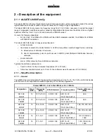
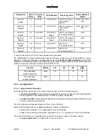
For the 13 GHz and the 23 to 38 GHz frequency bands, the transmitted power can be adjusted in 1 dB steps
by software configuration (software key option needed), within a range of:
--
--20 dB from nominal output power for 13 GHz (94xxUXR202 and 94xxUXR203),
--
--30 dB from nominal output power for 15, 23, 25, 38 GHz (4QAM RTPC),
--
--20 dB from nominal output power for 23, 25, 38 GHz (94xxUXR203 16QAM).
--
--30 dB from nominal output power for all frequency bands of the ODU 9400UX flat ODU.
For the 13, 15 and 18 GHz frequency bands (without RTPC option), attenuators can be inserted on the transmit
output (optional).
The receive RF signal from the branching filter, is applied to the RF receive circuit, comprising a cascaded RF
low noise amplifier (except at 38 GHz), a mixer and an IF amplifier. The mixer, which receives the amplified
RF frequency, transposes the RF signal to a receive IF signal using the same LO as the transmit mixer.
When amplified, the signal is sent to the IF block’s receive circuits for demodulation.
The branching filter comprises a duplexed filter for separating the transmit and receive RF signals present at
the antenna port. It can accommodate the RF loopback (94xxUXR201, 94xxUXR202 and 94xxUXR203, and
included into A9400UX flat ODU), which uses a conversion stage for converting transmit and receive
frequencies for test purposes.
The PSU receives the primary voltage from the IDU via the link cable and, from it, generates the voltages
required to operate the subsystems of the Outdoor unit.
2.2.1.5 -- ESC extension configuration
This extension, available only in the classic IDU version, can be used to customize ESC N
_
3 and N
_
4 and
5 as detailed in § 2.3. It requires the presence of an extension IDU with a dedicated SCU (Service Channel Unit)
board.
2.2.2 -- Basic 1+1 configuration
This configuration is available only in the classic IDU version.
It comprises (Figure 8) a main IDU (identical to the one in the 1+0 configuration), an extension IDU and two
ODUs.
The extension unit contains a Service Channel Unit (SCU) which handles the following functions:
--
provision of the user interfaces for ESCs 3 to 5,
--
control of the second ODU,
--
interfacing of the second ODU’s link cable.
The MCU of the main unit sends the SCU the aggregate to be transmitted and receives the receive aggregate
from it. The MCU is responsible, in reception, for switching between the normal and standby channels.
There are three configurations:
--
Hot Standby (HSB), one antenna port
--
Hot Standby, two antenna ports
--
Frequency diversity.
Summary of Contents for 9400 UX
Page 1: ...3CC08991ATAA TQBJA 01 Alcatel 9400 UX User Manual ...
Page 4: ...4 314 3CC08991ATAA TQ BJA 01 Issue 01 March 2004 PAGE INTENTIONALLY LEFT BLANK ...
Page 6: ...6 314 3CC08991ATAA TQ BJA 01 Issue 01 March 2004 PAGE INTENTIONALLY LEFT BLANK ...
Page 14: ...14 314 3CC08991ATAA TQ BJA 01 Issue 01 March 2004 PAGE INTENTIONALLY LEFT BLANK ...
Page 19: ...19 314 3CC08991ATAA TQ BJA 01 Issue 01 March 2004 1 3 5 Eco Declaration ...

