35/314
3CC08991ATAA TQ BJA 01
Issue 01 -- March 2004
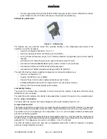
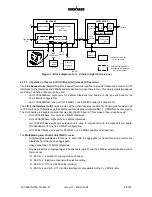
Figure 8 - Block diagram of 1+1 station
EXTENSION INDOOR UNIT
DC
Tributaries
1 to 16
One 2 Mbit/s aux.
bit stream
(only at 34 Mbit/s)
MAIN INDOOR UNIT
Cable
NMS
(Supervision
bus)
Back
to
back
TS/TC
alarms
To
coupler
or
Antenna
Mediation
device
ESC
3/4/5
OUTDOOR
UNIT
Cable
Tel.
To
coupler
or
Antenna
EXT
DC
OUTDOOR
UNIT
Equipment not included in the standard configuration but sold as options
EOW3 EOW4 EOW5
Service
kit
Service
kit
F
Alcatel or
Customer
OS
or
(RQ2)
(SNMP)
Software
key
2.2.2.1 -- HSB configuration with one antenna port
The two ODUs are connected by an HSB coupler which provides a 10 dB attenuation on the standby channel.
In addition, by design, the standby amplifier’s power is:
--
reduced by 15 dB for the ODU which does not permit an output power control,
--
cut off for the ODU which permits the output power control.
The HSB switching of a transmitter is based on detection of a fault which can originate from a failure:
--
of the cable interface,
--
of the ODU power supply,
--
of the transmit IF synthesizer,
--
of the RF synthesizer,
--
of the amplifier.
The system switches back to the normal channel automatically as soon as it is disconnected and reconnected
again without alarm (because of imbalance in the system), in transmission and in reception.
Switching can also be remotely controlled, by manually switching to the standby channel. The remote control
for cutting off transmit power does not cause a switchover.
2.2.2.2 -- HSB configuration with two antenna ports
This configuration uses either a double polarization antenna or two antennas (in this case, it also adds space
diversity). One system sends (the standby transmitter is cut off). Operation is the same as in the previous
configuration, apart from the switching, in which reversibility is not required because the link budgets are
identical for both channels.
2.2.2.3 -- Frequency diversity configuration
The two ODUs send the aggregate simultaneously at two different frequencies. The MCU chooses the best
of the two signals on reception. This configuration also uses two antenna ports.
Summary of Contents for 9400 UX
Page 1: ...3CC08991ATAA TQBJA 01 Alcatel 9400 UX User Manual ...
Page 4: ...4 314 3CC08991ATAA TQ BJA 01 Issue 01 March 2004 PAGE INTENTIONALLY LEFT BLANK ...
Page 6: ...6 314 3CC08991ATAA TQ BJA 01 Issue 01 March 2004 PAGE INTENTIONALLY LEFT BLANK ...
Page 14: ...14 314 3CC08991ATAA TQ BJA 01 Issue 01 March 2004 PAGE INTENTIONALLY LEFT BLANK ...
Page 19: ...19 314 3CC08991ATAA TQ BJA 01 Issue 01 March 2004 1 3 5 Eco Declaration ...

