83/314
3CC08991ATAA TQ BJA 01
Issue 01 -- March 2004
3.5.4.1 -- Installing the ODU 94
XX
UXR201, 94
XX
UXR202, 94
XX
UXR203
--
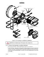
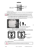
Remove the solar shield by undoing the M6 fixing screw with a 16 mm flat wrench.
--
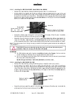
Take the ODU by the handle, offer up the two protrusion bosses located inside the “nose” of the unit
and facing the two grooves in the “nose” of the antenna (the ODU-IDU connecting cable entry should
be located in the bottom part of the ODU). Still holding the ODU, engage without fastening the top
catch on the support, begin by fastening the two side catches on the support, then fasten the bottom
catch, to complete with the top catch.
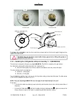
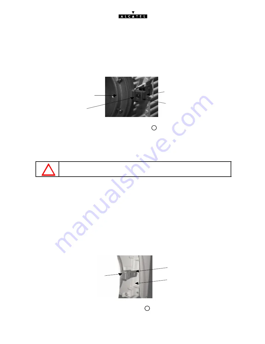
Position of catch for F < 20 GHz for
ODU from 94xxUXR201 to 94xxUXR203
Position of catch for F > 20
GHz
for
ODU
from
94xxUXR201 to 94xxUXR203
Catch bead
Support plate A
--
Swivel the antenna support through 90
on its azimuthal axis to release it from the pole. Immobilize
the vertical axis by the five screws (see Figure 32, item 3 ).
--
Reposition the solar shield via the back of the ODU, centre the bottom ribs of the solar shield in the
“grooves” of the ODU. Slide fully home, and moderately tighten by hand the screw (M6) in the recess
on the underside of the ODU. Check the assembly by trying to extract the solar shield from its recess.
Note: The locking screw is not a fixing, it is simply intended to safeguard against inadvertent dismantling; do
not overtighten.
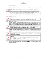
CAUTION: If the screw cannot be reached by hand, use a 16 mm flat wrench (as an
indication, fasten to a torque of 1mN, that is 0.1mdaN).
REMINDER:
S
The ODU/antenna assembly requires no additional seal on the flanges; the two ends are
smooth. Sealing is provided by the O--ring seal around the male “noses”.
S
For a 1+0 configuration, when the ODU is fitted, the polarization of the antenna can be ascertained
from the position of the ODU handle:
handle arranged vertically = horizontal polarization, and vice versa.
3.5.4.2 -- Installing the ODU 9400UX flat ODU
--
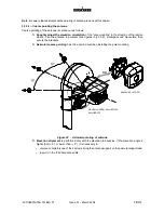
Remove the solar shield by undoing the M4 fixing screw manually or with a screw driver.
--
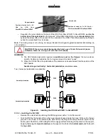
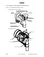
Take the ODU by the handle, offer up the two bosses located inside the “nose” of the unit and facing
the two grooves in the “nose” of the antenna (the ODU-IDU connecting cable entry should be located
in the bottom part of the ODU). Still holding the ODU, engage without fastening the top catch on the
support, begin by fastening the two side catches on the support, then fasten the bottom catch, to
complete with the top catch.
Flat ODU
Position of catch for
A9400UX flat ODU
Catch bead
--
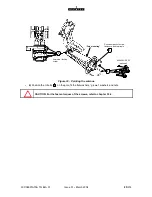
Swivel the antenna support through 90
on its azimutal axis to release it from the pole. Immobilize the
vertical axis by the five screws (see Figure 32, item 3 ).
Summary of Contents for 9400 UX
Page 1: ...3CC08991ATAA TQBJA 01 Alcatel 9400 UX User Manual ...
Page 4: ...4 314 3CC08991ATAA TQ BJA 01 Issue 01 March 2004 PAGE INTENTIONALLY LEFT BLANK ...
Page 6: ...6 314 3CC08991ATAA TQ BJA 01 Issue 01 March 2004 PAGE INTENTIONALLY LEFT BLANK ...
Page 14: ...14 314 3CC08991ATAA TQ BJA 01 Issue 01 March 2004 PAGE INTENTIONALLY LEFT BLANK ...
Page 19: ...19 314 3CC08991ATAA TQ BJA 01 Issue 01 March 2004 1 3 5 Eco Declaration ...

