15 — E1 module operating parameters
15-6
2902 MainStreet Technical Practices
90-2906-01 May
2002
15.5
Master/slave operation (E1 HDSL and Optical LIMs only)
To establish a link, the E1 HDSL or Optical LIM at each end of the link must be
configured as either a master or slave LIM. However, both LIMs cannot have the
same configuration. The E1 HDSL LIMs do not connect any of the HDSL signal
leads to ground (as do the E1 G.703 LIMs) because HDSL is a balanced signal
interface.
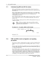
Procedure 15-4 To configure master/slave operation for E1 HDSL
and Optical LIMs
The method you use to configure master/slave operation for the E1 HDSL LIM2 depends
on the node software generic you are using. The node software generic does not affect
the configuration method for the E1 HDSL LIM or Optical LIM.
If you are using an E1 HDSL LIM2 on a 2902 MainStreet node with software generic
82211-H0-00 or 82211-H0-01, you must use the BNC transmit shield option to program
the LIM to be a master or slave. By default, the BNC shield option is set to TX_EARTH,
which corresponds to the master mode on an E1 HDSL LIM2. To program one of the E1
HDSL LIM2s for slave mode, the BNC transmit shield option must be configured for
floating.
For E1 HDSL LIM2s with software generic 82211-H0-00 or 82211-H0-01, enter:
where
p
is 1 or 2
* Default
Caution —
If the E1 HDSL or Optical LIM at each end of a link is
configured as the same type (for example, master-to-master or
slave-to-slave), the E1 HDSL or Optical LIMs cannot synchronize.
Note —
Once the HDSL or optical link is connected and the modules
are programmed for either master or slave mode, it takes
approximately 60 seconds for the HDSL or optical interfaces to
synchronize. This time can also apply when loopbacks are applied or
the link is in a fault condition.
BNC_SHIELD
RX_EARTH*/RX_FLOAT
TX_EARTH*/TX_FLOAT
CONFIG — POSITION — <P
p
>
↵
— OPTIONS
SK000678
Summary of Contents for MainStreet 2902
Page 1: ...2902 MainStreet Network Termination Unit Release 1 0 H T E C H N I C A L P R A C T I C E S ...
Page 40: ...3 Mounting the unit 3 8 2902 MainStreet Technical Practices 90 2906 01 May 2002 ...
Page 50: ...4 Ground and power connections 4 10 2902 MainStreet Technical Practices 90 2906 01 May 2002 ...
Page 68: ...6 Connecting to the network 6 4 2902 MainStreet Technical Practices 90 2906 01 May 2002 ...
Page 90: ...7 Connecting to data devices 7 22 2902 MainStreet Technical Practices 90 2906 01 May 2002 ...
Page 108: ...10 Node management 10 10 2902 MainStreet Technical Practices 90 2906 01 May 2002 ...
Page 150: ...14 CPSS 14 6 2902 MainStreet Technical Practices 90 2906 01 May 2002 ...
Page 218: ...20 Codirectional DCM 20 6 2902 MainStreet Technical Practices 90 2906 01 May 2002 ...
Page 234: ...22 HCM rate adaption 22 10 2902 MainStreet Technical Practices 90 2906 01 May 2002 ...
Page 246: ...23 Cross connecting circuits 23 12 2902 MainStreet Technical Practices 90 2906 01 May 2002 ...
Page 254: ...24 Visual indicators 24 8 2902 MainStreet Technical Practices 90 2906 01 May 2002 ...
Page 266: ...25 Alarms 25 12 2902 MainStreet Technical Practices 90 2906 01 May 2002 ...
Page 278: ...26 System diagnostics 26 12 2902 MainStreet Technical Practices 90 2906 01 May 2002 ...
Page 298: ...27 Loopbacks 27 20 2902 MainStreet Technical Practices 90 2906 01 May 2002 ...
Page 332: ...Glossary GL 8 2902 MainStreet Technical Practices 90 2906 01 May 2002 ...
Page 343: ......
Page 344: ... 2002 Alcatel All rights reserved 90 2906 01 95 1820 01 00 C ...


