17 — DNIC and 2B1Q modules
17-2
2902 MainStreet Technical Practices
90-2906-01 May
2002
17.1
Understanding DNIC and 2B1Q modules
DNIC and 2B1Q modules are dual-circuit modules that connect to data devices
through DTUs. These modules can be installed in either interface module position on
the Control card.
DNIC modules support remote connections of up to two X.21 or V.35 data devices,
and up to eight EIA/TIA-232 data devices via a 2600 MainStreet series DTU; 2B1Q
modules support up to two EIA/TIA-232, X.21 or V.35 data devices via
2700 MainStreet series DTUs.
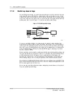
DNIC and 2B1Q modules support subrate interface speeds up to 64 kb/s, a super-rate
speed of 128 kb/s (see section 17.11) and multidrop data bridge connections (see
section 17.10).
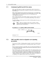
You must configure a module position for a DNIC or 2B1Q module before you can
configure its circuits.
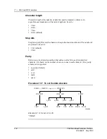
Procedure 17-1 To specify a DNIC or 2B1Q module
where
pp
is 1 or 9
17.2
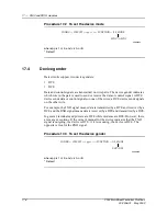
DNIC and 2B1Q circuit configuration and operating
parameters
The circuits on a DNIC or 2B1Q module are numbered A and B. The DNIC module
connects to two-port or eight-port DTUs. The 2B1Q module connects to two-port
DTUs.
When a module is used with a two-port DTU, circuit A communicates with DTU port
A and circuit B communicates with DTU port B. Each circuit (that is, DTU port) can
be configured independently.
When a DNIC module is used with an eight-port DTU, the combined interface speed
of the connected data devices can be less than, equal to, or greater than 64 kb/s. If it
is less than or equal to 64 kb/s, circuit A serves all the devices. If it is greater than
64 kb/s, circuits A and B serve all the devices. In either case, circuit parameters are
configured through circuit B, which sets both DTU ports with the same parameters.
Configuring circuit A parameters has no effect on the connection.
Note —
When you configure a data circuit on a DNIC or 2B1Q
module, many of the parameters you are configuring are the operating
parameters of the connected DTU.
DNIC
2B1Q
CONFIG — POSITION — <
pp
>
↵
— TYPE — DATA
SK000494
Summary of Contents for MainStreet 2902
Page 1: ...2902 MainStreet Network Termination Unit Release 1 0 H T E C H N I C A L P R A C T I C E S ...
Page 40: ...3 Mounting the unit 3 8 2902 MainStreet Technical Practices 90 2906 01 May 2002 ...
Page 50: ...4 Ground and power connections 4 10 2902 MainStreet Technical Practices 90 2906 01 May 2002 ...
Page 68: ...6 Connecting to the network 6 4 2902 MainStreet Technical Practices 90 2906 01 May 2002 ...
Page 90: ...7 Connecting to data devices 7 22 2902 MainStreet Technical Practices 90 2906 01 May 2002 ...
Page 108: ...10 Node management 10 10 2902 MainStreet Technical Practices 90 2906 01 May 2002 ...
Page 150: ...14 CPSS 14 6 2902 MainStreet Technical Practices 90 2906 01 May 2002 ...
Page 218: ...20 Codirectional DCM 20 6 2902 MainStreet Technical Practices 90 2906 01 May 2002 ...
Page 234: ...22 HCM rate adaption 22 10 2902 MainStreet Technical Practices 90 2906 01 May 2002 ...
Page 246: ...23 Cross connecting circuits 23 12 2902 MainStreet Technical Practices 90 2906 01 May 2002 ...
Page 254: ...24 Visual indicators 24 8 2902 MainStreet Technical Practices 90 2906 01 May 2002 ...
Page 266: ...25 Alarms 25 12 2902 MainStreet Technical Practices 90 2906 01 May 2002 ...
Page 278: ...26 System diagnostics 26 12 2902 MainStreet Technical Practices 90 2906 01 May 2002 ...
Page 298: ...27 Loopbacks 27 20 2902 MainStreet Technical Practices 90 2906 01 May 2002 ...
Page 332: ...Glossary GL 8 2902 MainStreet Technical Practices 90 2906 01 May 2002 ...
Page 343: ......
Page 344: ... 2002 Alcatel All rights reserved 90 2906 01 95 1820 01 00 C ...


