23 — Cross-connecting circuits
2902 MainStreet Technical Practices
23-7
May 2002 90-2906-01
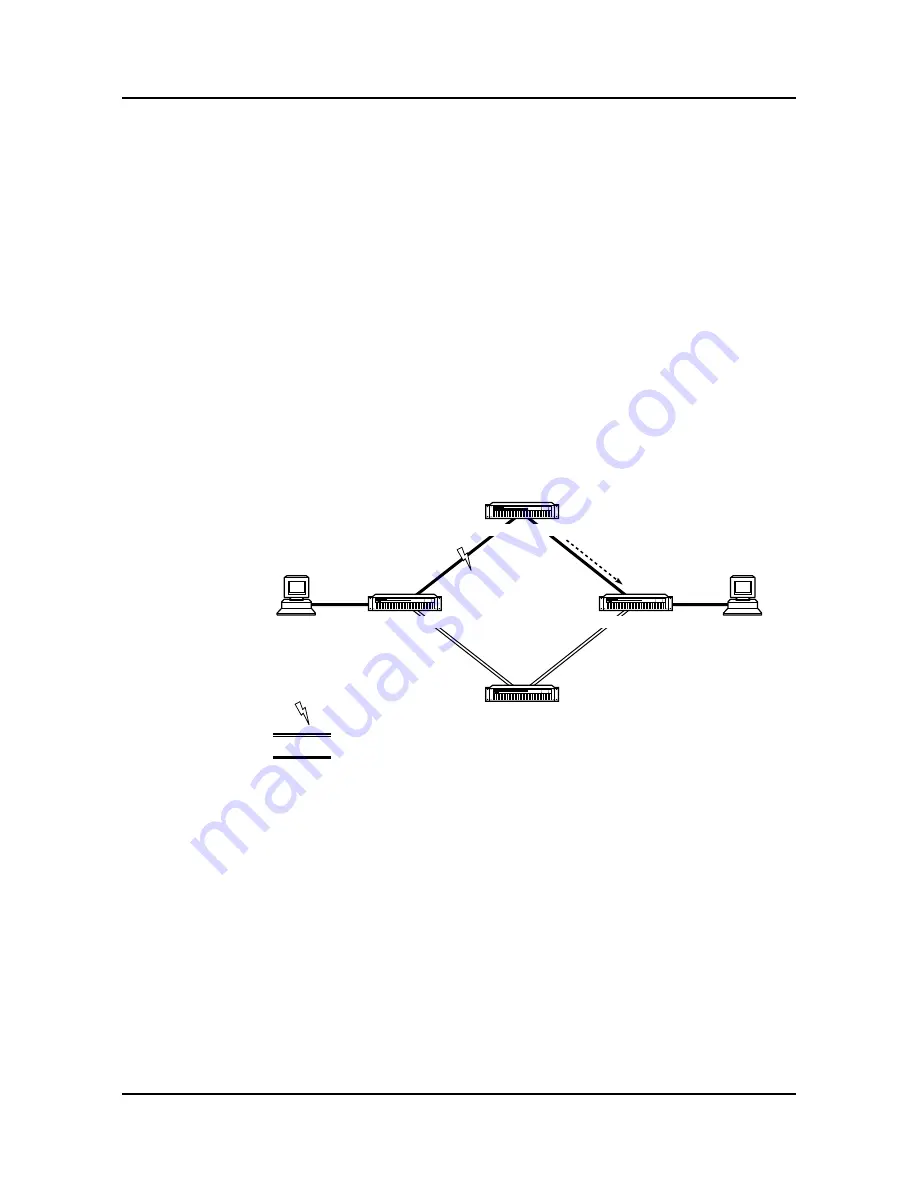
Figure 23-4 shows an example of protection switching that involves tandem nodes.
Each node #1 circuit on link E1(1) is protected by a circuit on link E1(3). Each
node #3 circuit on link E1(2) is protected by a circuit on link E1(4). If link E1(1)
fails:
1 An alarm is raised at node #1 and protection switching occurs; that is, the
protected circuits are connected to their protecting circuits on link E1(3).
2 The fault signaling configured at node #2 is carried to node #3 on link E1(2). By
configuring the circuits on link E1(1) for out-of-service signaling at node #2,
node #3 is informed that link E1(1) is down.
3 Node #3 switches the protected circuits on link E1(2) to their protecting circuits
on link E1(4).
If the circuits on link E1(1) are configured for seized or idle fault signaling at node #2
(instead of OOS-A or OOS-B fault signaling), node #3 is not informed that link E1(1)
is down. In this case, node #3 does not switch the circuits on link E1(2) to their
protecting circuits on link E1(4).
Figure 23-4 Out-of-service signaling for tandem nodes
Pointers for protecting circuits
It is possible to share a protecting circuit, using it for one connection while it waits
to switch to its protecting mode. If a protection switch occurs, the original connection
is automatically overridden by the protecting connection.
There are several situations when protecting circuits should be used with caution,
including:
•
automatic override
•
incompatible far-end devices
•
circuits on the same link
E1(1)
E1(2)
E1(3)
E1(4)
Out-of-service
fault signaling
Active (and preferred) connection
Protecting connection
Fault
8874
2902 MainStreet
node #2
2902 MainStreet
node #4
2902 MainStreet
node #3
2902 MainStreet
node #1
Data
device
Data
device
Summary of Contents for MainStreet 2902
Page 1: ...2902 MainStreet Network Termination Unit Release 1 0 H T E C H N I C A L P R A C T I C E S ...
Page 40: ...3 Mounting the unit 3 8 2902 MainStreet Technical Practices 90 2906 01 May 2002 ...
Page 50: ...4 Ground and power connections 4 10 2902 MainStreet Technical Practices 90 2906 01 May 2002 ...
Page 68: ...6 Connecting to the network 6 4 2902 MainStreet Technical Practices 90 2906 01 May 2002 ...
Page 90: ...7 Connecting to data devices 7 22 2902 MainStreet Technical Practices 90 2906 01 May 2002 ...
Page 108: ...10 Node management 10 10 2902 MainStreet Technical Practices 90 2906 01 May 2002 ...
Page 150: ...14 CPSS 14 6 2902 MainStreet Technical Practices 90 2906 01 May 2002 ...
Page 218: ...20 Codirectional DCM 20 6 2902 MainStreet Technical Practices 90 2906 01 May 2002 ...
Page 234: ...22 HCM rate adaption 22 10 2902 MainStreet Technical Practices 90 2906 01 May 2002 ...
Page 246: ...23 Cross connecting circuits 23 12 2902 MainStreet Technical Practices 90 2906 01 May 2002 ...
Page 254: ...24 Visual indicators 24 8 2902 MainStreet Technical Practices 90 2906 01 May 2002 ...
Page 266: ...25 Alarms 25 12 2902 MainStreet Technical Practices 90 2906 01 May 2002 ...
Page 278: ...26 System diagnostics 26 12 2902 MainStreet Technical Practices 90 2906 01 May 2002 ...
Page 298: ...27 Loopbacks 27 20 2902 MainStreet Technical Practices 90 2906 01 May 2002 ...
Page 332: ...Glossary GL 8 2902 MainStreet Technical Practices 90 2906 01 May 2002 ...
Page 343: ......
Page 344: ... 2002 Alcatel All rights reserved 90 2906 01 95 1820 01 00 C ...


