Page 12-2
Stratum
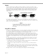
Stratum is the term used to define the relative proximity of a node in a network to a time
source (such as a radio clock). Stratum 1 is the server connected to the time source itself. (In
most cases the time source and the stratum 1 server are in the same physical location.) An
NTP
client or server connected to a stratum 1 source would be stratum 2. A client or server
connected to a stratum 2 machine would be stratum 3, and so on, as demonstrated in the
diagram below.
The farther away from stratum 1 a device is, the more likely there will be discrepancies or
errors in the time adjustments done by NTP. A list of stratum 1 and 2 sources available to the
public can be found on the Internet.
♦
Note
♦
It is not required that NTP be connected to an officially
recognized time source (for example, a radio clock).
NTP can use any time source to synchronize time in
the network.
Using NTP in a Network
NTP
operates on the premise that there is one true standard time (defined by
UTC
), and that if
several servers claiming synchronization to the standard time are in disagreement, then one or
more of them must be out of synchronization or not functioning correctly.
The stratum gradiation is used to qualify the accuracy of a time source along with other
factors such as advertised precision and the length of the network path between connections.
NTP
operates with a basic distrust of time information sent from other network entities, and is
most effective when multiple
NTP
time sources are integrated together for checks and cross-
checks.
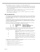
To achieve this end, there are several modes of operation that an
NTP
entity can use when
synchronizing time in a network. These modes help predict how the entity behaves when
requesting or sending time information, listed below:
• A switch can be a client of an
NTP
server (usually of a lower stratum), receiving time infor-
mation from the server but not passing it on to other switches.
• A switch can be a client of an
NTP
server, and in turn be a server to another switch or
switches.
• A switch (regardless of its status as either a client or server) must be
peered
with another
switch. Peering allows
NTP
entities in the network of the same stratum to regard each other
as reliable sources of time and exchange time information.
Examples of these are shown in the simple network diagram on the following page:
Time Source
Omni Switch/Routers running NTP
Stratum 1
Stratum 2
Stratum 3
(UTC)
Summary of Contents for Omni Switch/Router
Page 1: ...Part No 060166 10 Rev C March 2005 Omni Switch Router User Manual Release 4 5 www alcatel com ...
Page 4: ...page iv ...
Page 110: ...WAN Modules Page 3 40 ...
Page 156: ...UI Table Filtering Using Search and Filter Commands Page 4 46 ...
Page 164: ...Using ZMODEM Page 5 8 ...
Page 186: ...Displaying and Setting the Swap State Page 6 22 ...
Page 202: ...Creating a New File System Page 7 16 ...
Page 270: ...Displaying Secure Access Entries in the MPM Log Page 10 14 ...
Page 430: ...OmniChannel Page 15 16 ...
Page 496: ...Configuring Source Route to Transparent Bridging Page 17 48 ...
Page 542: ...Dissimilar LAN Switching Capabilities Page 18 46 ...
Page 646: ...Application Example DHCP Policies Page 20 30 ...
Page 660: ...GMAP Page 21 14 ...
Page 710: ...Viewing the Virtual Interface of Multicast VLANs Page 23 16 ...
Page 722: ...Application Example 5 Page 24 12 ...
Page 788: ...Viewing UDP Relay Statistics Page 26 24 ...
Page 872: ...The WAN Port Software Menu Page 28 46 ...
Page 960: ...Deleting a PPP Entity Page 30 22 ...
Page 978: ...Displaying Link Status Page 31 18 ...
Page 988: ...Displaying ISDN Configuration Entry Status Page 32 10 ...
Page 1024: ...Backup Services Commands Page 34 14 ...
Page 1062: ...Diagnostic Test Cable Schematics Page 36 24 ...
Page 1072: ...Configuring a Switch with an MPX Page A 10 ...
Page 1086: ...Page B 14 ...
Page 1100: ...Page I 14 Index ...

