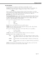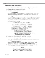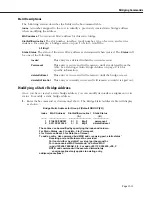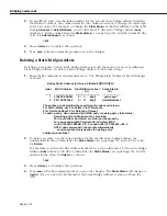
Configuring Spanning Tree
Page 17-23
Configuring Spanning Tree
Spanning Tree is an algorithm developed to help prevent the occurrence of broadcast storms
in a network. A packet can be broadcast multiple times in a network if the network is physi-
cally configured with loops.
If packets are broadcast to all ports (or flooded) in an attempt to deliver the data, networks
with physical loops will rebroadcast packets repeatedly and cause a network to become
severely congested. This congestion will adversely affect network performance.
Spanning Tree prevents broadcast storms by establishing a loop-free topology throughout the
network. This is done by blocking ports in the physical topology that could result in flooded
traffic being looped.
Both the IEEE and IBM versions of spanning tree are supported in the OmniSwitch/Router.
The IBM Spanning Tree protocol is only supported by IBM Token Ring environments that
make use of functional addresses for the transmission of Bridge Protocol Data Units (BPDUs).
The following are the primary differences between the IEEE 802.1d and IBM Spanning Tree
algorithms:
• The Hello BPDU in IBM Spanning Tree is sent to the bridge functional address,
X’C00000000100’. In the IEEE 802.1d Spanning Tree, it is sent to the Group address
X’800143000000’.
• The Port ID in IBM Spanning Tree consists of a ring identifier and a bridge number. In
802.1d, it consists of a port priority and port number.
• IBM Spanning Tree has no learning process. Therefore, a port can be in one of three
states—blocking, listening, or forwarding.
• IBM Spanning Tree does not support the Topology Change Notification (TCN) protocol.
• When you enable IBM Spanning Tree, the switch automatically sets defaults for the maxi-
mum age, forward delay, and hello time. In the interests of screen consistency, it is possi-
ble to change these defaults with the UI. In IBM Spanning Tree specification, these values
are fixed, and should remain at the set defaults.
• When you enable IBM Spanning Tree, some additional defaults are set:
– All virtual ports attached to the group with a physical port speed of 4 or 16
Mb are set to use Functional Addresses rather than Group Addresses.
– All virtual ports attached to the group with a physical port speed that is not
4 or 16 Mb are set to manual forwarding.
– As other virtual ports are attached to the group, the above two rules are
applied.
Virtual ports in a manual forwarding state do not participate in either the IEEE or IBM
versions of spanning tree. Any IEEE Spanning Tree frame received on a port in a manual
forwarding state is forwarded to all other virtual ports in the same group also in a manual
forwarding state. This is done to prevent loops from occurring in the network topology
that could arise from applying the second default condition automatically.
Summary of Contents for Omni Switch/Router
Page 1: ...Part No 060166 10 Rev C March 2005 Omni Switch Router User Manual Release 4 5 www alcatel com ...
Page 4: ...page iv ...
Page 110: ...WAN Modules Page 3 40 ...
Page 156: ...UI Table Filtering Using Search and Filter Commands Page 4 46 ...
Page 164: ...Using ZMODEM Page 5 8 ...
Page 186: ...Displaying and Setting the Swap State Page 6 22 ...
Page 202: ...Creating a New File System Page 7 16 ...
Page 270: ...Displaying Secure Access Entries in the MPM Log Page 10 14 ...
Page 430: ...OmniChannel Page 15 16 ...
Page 496: ...Configuring Source Route to Transparent Bridging Page 17 48 ...
Page 542: ...Dissimilar LAN Switching Capabilities Page 18 46 ...
Page 646: ...Application Example DHCP Policies Page 20 30 ...
Page 660: ...GMAP Page 21 14 ...
Page 710: ...Viewing the Virtual Interface of Multicast VLANs Page 23 16 ...
Page 722: ...Application Example 5 Page 24 12 ...
Page 788: ...Viewing UDP Relay Statistics Page 26 24 ...
Page 872: ...The WAN Port Software Menu Page 28 46 ...
Page 960: ...Deleting a PPP Entity Page 30 22 ...
Page 978: ...Displaying Link Status Page 31 18 ...
Page 988: ...Displaying ISDN Configuration Entry Status Page 32 10 ...
Page 1024: ...Backup Services Commands Page 34 14 ...
Page 1062: ...Diagnostic Test Cable Schematics Page 36 24 ...
Page 1072: ...Configuring a Switch with an MPX Page A 10 ...
Page 1086: ...Page B 14 ...
Page 1100: ...Page I 14 Index ...

