Using the PING Command
Page 25-23
5.
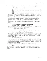
After answering the previous prompt, a screen similar to the following displays:
Ping starting, hit <RETURN> to stop
PING 198.206.184.18: 64 data bytes
[0
]
. . . . .
. . . . .
. . . . .
. . . . .
. . . . .
. . . . .
. . . . .
. . . . .
. . . . .
. T. . .
[50
]
. . . T.
. . . . .
. . . . .
. . . . .
. . . . .
. . . . .
. . . . .
. . . . .
. . . . .
. . . . .
[100
]
. . . . .
. . . . .
. . . . .
. . . . .
. . . . .
. . . . .
. . . . .
. . . . .
. . . . .
. . . . .
[150
]
. . . . .
. . . . .
. . . . .
. . . . .
. . . . .
. . . . .
. . . . .
. . . . .
. . . . .
. . . . .
[200
]
. . . . .
. . . . .
. . . . .
. . . . .
. . . . .
. . . . .
. . . . .
. . . . .
. . . . .
. . . . .
[250
]
. . . . .
. . . . .
. . . . .
. . . . .
. . . . .
. . . . .
. . .
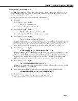
This screen shows the progress of the ping operation as it is taking place. The numbers in
the square brackets indicate how many packets have been transmitted for that row. The
periods to the right of the brackets represent packets as they are exchanged between the
switch and the device owning the IP address entered for the ping.
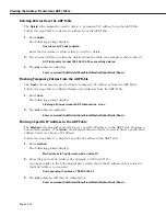
A period (
.
) indicates a packet that was sent out by the switch and came back to the
switch. Occasionally, you may see a
T
character in place of a period. A
T
indicates a
packet that was sent out and never came back to the switch (or a “lost” packet).
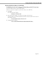
When you press
Enter
, the ping operation stops and a screen similar to the following
displays.
----198.206.184.18 PING Statistics----
283 packets transmitted, 281 packets received, 0% packet loss
Round-trip
(ms)
min/avg/max
=
6/28/638
This display shows a recap of the
ping
request just completed and its results. The screen
shown in this example indicates a successful ping operation.
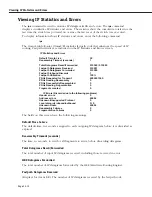
-- -- PING 198.206.184.18 PING Statistics -- --
This display indicates the IP address of the device the switch tried to ping. This is the
same IP address entered in step 1 of the ping request.
283 packet transmitted, 281 packets received, 0% packet loss
The first value indicates the total number of packets transmitted from the switch to the IP
address. The second value indicates the total number of packets received by the switch,
back from the IP address. The third value indicates the percent of packets lost of those
originally transmitted.
Round-trip (ms) min/avg/max
These values indicate the amount of time it took for the ping to be sent, received by the
other device, replied to by the other device and received back by the switch. Because the
amount of time needed to complete a round-trip will vary, three values are given to indi-
cate the minimum, maximum and the average time taken to complete a round-trip. These
values are shown in milliseconds.
To repeat the last ping request, enter the following command at the system prompt:
fping
The last ping issued on the switch is immediately sent again. If no ping was previously
issued, a prompt for the host address displays and defaults are used for Count, Size, and
Timeout.
Summary of Contents for Omni Switch/Router
Page 1: ...Part No 060166 10 Rev C March 2005 Omni Switch Router User Manual Release 4 5 www alcatel com ...
Page 4: ...page iv ...
Page 110: ...WAN Modules Page 3 40 ...
Page 156: ...UI Table Filtering Using Search and Filter Commands Page 4 46 ...
Page 164: ...Using ZMODEM Page 5 8 ...
Page 186: ...Displaying and Setting the Swap State Page 6 22 ...
Page 202: ...Creating a New File System Page 7 16 ...
Page 270: ...Displaying Secure Access Entries in the MPM Log Page 10 14 ...
Page 430: ...OmniChannel Page 15 16 ...
Page 496: ...Configuring Source Route to Transparent Bridging Page 17 48 ...
Page 542: ...Dissimilar LAN Switching Capabilities Page 18 46 ...
Page 646: ...Application Example DHCP Policies Page 20 30 ...
Page 660: ...GMAP Page 21 14 ...
Page 710: ...Viewing the Virtual Interface of Multicast VLANs Page 23 16 ...
Page 722: ...Application Example 5 Page 24 12 ...
Page 788: ...Viewing UDP Relay Statistics Page 26 24 ...
Page 872: ...The WAN Port Software Menu Page 28 46 ...
Page 960: ...Deleting a PPP Entity Page 30 22 ...
Page 978: ...Displaying Link Status Page 31 18 ...
Page 988: ...Displaying ISDN Configuration Entry Status Page 32 10 ...
Page 1024: ...Backup Services Commands Page 34 14 ...
Page 1062: ...Diagnostic Test Cable Schematics Page 36 24 ...
Page 1072: ...Configuring a Switch with an MPX Page A 10 ...
Page 1086: ...Page B 14 ...
Page 1100: ...Page I 14 Index ...

