Configuring a T1 Port
Page 33-4
Configuring a T1 Port
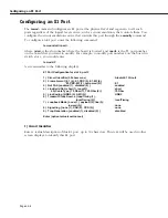
The
temod
command configures a T1 port at the physical level and is generic to all such ports
regardless of the logical level service, such as circuit emulation, that controls them.
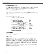
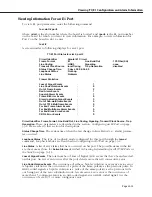
To configure a T1 port, enter the following command
temod <slot>/<port>
where
<slot>
is the slot number where the board is located, and
<port>
is the T1 port number
on the board that you want to modify. For example, to modify port number 2 on the board in
switch slot 5, enter
temod 5/2
A screen similar to the following displays:
T1 Port Configuration for slot 5, port 2
1) Circuit Identifier (30 chars max)
: Alcatel T1 Circuit
2) Frame Format { ESF (2), SF (3), unframed (8) }
: ESF
3) Line Build Out { short(1), long(2) }
: short
30) Line Length in meters (0-200)
: 30
4) Line Coding { B8ZS (2) , AMI (5) }
: B8ZS
5) Facility Datalink { ANSI T1.403 (2), AT&T 54016 (4),
T1.403-AT&T (6), none (8) }
: none
6) Facility Datalink Port Role { network (1), user (2) }
: network
7) Transmit Clock Source { loopTiming (1),
localTiming (2) }
: localTiming
8) Loopback Mode { none (1), payload (2), line (3),
inward (5) }
: inward
9) Signalling { none (1), CAS (2), CCS (3) }
: none
10) Trap Generation { enabled (1), disabled (2) }
: disabled
11) Yellow Alarm Detection { enabled (1), disabled (2) }
: enabled
Enter (option=value/save/cancel) :
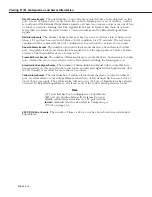
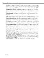
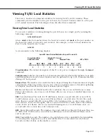
1) Circuit Identifier
Enter a textual description of this
T1
port, up to 30 characters. This text will be used in other
screen displays to identify this
T1
port.
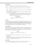
2) Frame Format
Specify the frame format to be used on this port. The choices are Extended SuperFrame
(
ESF
), SuperFrame or
D4
(
SF
), or no special frame format (
unframed
). A
T1
frame consists of
24 8-bit time slots and a 1-bit synchronization and control. Twelve (12)
T1
frames can be
grouped into a SuperFrame, and
24 T1
frames can be grouped into an Extended SuperFrame.
Normally, you should configure a T1 port as ESF (the default) since a T1 port configured as
SuperFrame (SF) can produce false yellow alarms if a Layer 2 protocol like High-Level Data
Link Control (HDLC) is being used.
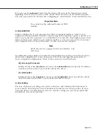
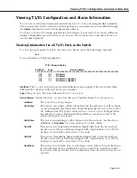
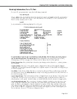
If you must set the port as SF, you can disable Yellow Alarm detection with the
Yellow Alarm
Detection
option, which is described on page 33-7.
Summary of Contents for Omni Switch/Router
Page 1: ...Part No 060166 10 Rev C March 2005 Omni Switch Router User Manual Release 4 5 www alcatel com ...
Page 4: ...page iv ...
Page 110: ...WAN Modules Page 3 40 ...
Page 156: ...UI Table Filtering Using Search and Filter Commands Page 4 46 ...
Page 164: ...Using ZMODEM Page 5 8 ...
Page 186: ...Displaying and Setting the Swap State Page 6 22 ...
Page 202: ...Creating a New File System Page 7 16 ...
Page 270: ...Displaying Secure Access Entries in the MPM Log Page 10 14 ...
Page 430: ...OmniChannel Page 15 16 ...
Page 496: ...Configuring Source Route to Transparent Bridging Page 17 48 ...
Page 542: ...Dissimilar LAN Switching Capabilities Page 18 46 ...
Page 646: ...Application Example DHCP Policies Page 20 30 ...
Page 660: ...GMAP Page 21 14 ...
Page 710: ...Viewing the Virtual Interface of Multicast VLANs Page 23 16 ...
Page 722: ...Application Example 5 Page 24 12 ...
Page 788: ...Viewing UDP Relay Statistics Page 26 24 ...
Page 872: ...The WAN Port Software Menu Page 28 46 ...
Page 960: ...Deleting a PPP Entity Page 30 22 ...
Page 978: ...Displaying Link Status Page 31 18 ...
Page 988: ...Displaying ISDN Configuration Entry Status Page 32 10 ...
Page 1024: ...Backup Services Commands Page 34 14 ...
Page 1062: ...Diagnostic Test Cable Schematics Page 36 24 ...
Page 1072: ...Configuring a Switch with an MPX Page A 10 ...
Page 1086: ...Page B 14 ...
Page 1100: ...Page I 14 Index ...


