18
2480 Remote Intensifier Tooling Alcoa Fastening Systems
FILL AND BLEED PROCEDURE FOR
DISASSEMBLED TOOLS
(Figures 11-13)
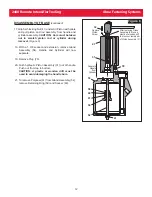
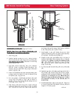
1. Before assembling Manifold Block onto Cylinder and
Handle assembly, push Air Piston (51) and intensifier
Piston Rod (52) assembly down to its full bottom
position. Use a nonmetallic rod to prevent damage to
handle bores and intensifier rods.
2. Fill handle pull and return ports with hydraulic fluid.
3. Install hose sleeves onto hoses and airline.
NOTE: Identify each end of one hose before
assembly.
Assemble the Manifold Block with Hoses
and Reservoirs onto the Handle.
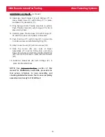
4. Attach Fill Bottles with Connector (Figure 11) to ends
of each Hydraulic Hose (63). With Handle lower than
the end of the Hoses and Fill Bottles, connect Tool to
40psi air, and cycle the intensifier to remove all air
from the Hoses. Remove fill bottles and keep Hoses
vertical. Disconnect Tool from air supply.
5. Push tool Piston (4) into the full forward position and
hold tool upside down. Fill PULL and RETURN ports
with hydraulic fluid.
6. With tool still upside down, carefully attach Hydraulic
Hoses. NOTE: A slight amount of fluid will be lost
from the Hoses at this point. This is acceptable.
CAUTION: Use protection under Tool and Base to
catch or absorb any hydraulic fluid which may
drip or spill. See WARNING in Figure 11.
7. Attach plastic Handle halves (19), with Air Trigger
Assembly attached, to sides of tool.
8. Connect 60 psi air to the Cylinder and cycle the tool
and measure the specified stroke.
9. To properly pressurize the system follow all
instructions in the F
ILL AND
B
LEED
P
ROCEDURE FOR
A
SSEMBLED
T
OOLS THAT
N
EED
R
E
-
BLEEDING
section of
this manual.
RETURN
PORT
PULL
PORT
Step 1
Push Air Piston (51) and
intensifier Piston Rod
(52) assembly down to
the full bottom position.
Air Piston (50)
Intensifier Piston
Rod (52)
Step 2
Fill handle PULL and
RETURN ports with
hydraulic fluid.
Figure 13
S
S
ER
ER
VICE
VICE
N
N
OTES
OTES


