SFBTT20-IT BOBTAIL® Hydraulic Tool
(HK1121)
Alcoa Fastening Systems
8
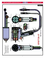
Load
Cell
Trigger
Switch
Test
Fastener
PHOTO - A
PHOTO - B
Tool Force
Tool Force
Reading
Reading
To decrease
Relief Valve pres-
sure, turn the
Relief Valve han-
dle gradually
counterclockwise;
turn clockwise to
increase pressure.
Relief
Relief
Valve
Valve
Fastener
Size and
Grade
Tool Force
(lbs)
Relief Valve
Pressure
(psi)
Powerig
PULL Pressure Setting
(psi)
Powerig
RETURN Pressure Setting
(psi)
Controller
Pressure Setting
(psi)i
1/2 inch
Grade 5
7800-8000
2700
7000
5000
2450
5/8 inch
Grade 8
20,500-21,000
6100
7000
5000
5850
12 mm
Grade 10.9
12,000-13,000
4250
7000
5000
4000
14 mm
Grade 10.9
16,000-17,000
5600
7000
5000
5350
16 mm
Grade 10.9
20,500-21,000
6100
7000
5000
5850
Table 1 - Tool Force and Pressure Settings
S
S
ETUP
ETUP
(
CONTINUED
)
11. Set Pull and Return pressures on Powerig
using Huck Gage P/N: T-124833CE and
Table 1
.
12. Using a load cell
(see
PHOTO-A
)
or a skid-
more, and a test fastener in the tool, energize
the Powerig using a trigger switch. Adjust the
Relief Valve
(see
PHOTO - B
)
so the tool gen-
erates the Tool Force shown in
Table 1
below.
This is a direct force reading, not pressure. It
equals approximately the Relief Valve
Pressure shown in
Table 1
.
NOTE: It is
important to Release the Trigger while
adjusting pressure, then re-energizing to
re-check pressure. Otherwise, the reading
on the pressure display may be incorrect.
When the desired pressure is achieved,
reconnect the Controller Cord.
13. Tool #2 and Tool #3 - Set up the same way as
Tool 1.
14. Once the system is set up, Install test fasten-
er. Check to be sure that the fastener is
installed correctly. This can be checked by
inspecting the dimples on the collar flange. At
least one dimple should be marked by the
anvil. If not, add time to Timer #2 (Hold Timer)
in the Controller box, and test with fasteners
until the proper installation is achieved. See
“Set Point Adjustments” in
C
ONTROLLER
sec-
tion on the next page to adjust timer.


