


11
11
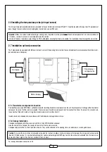
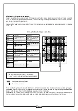
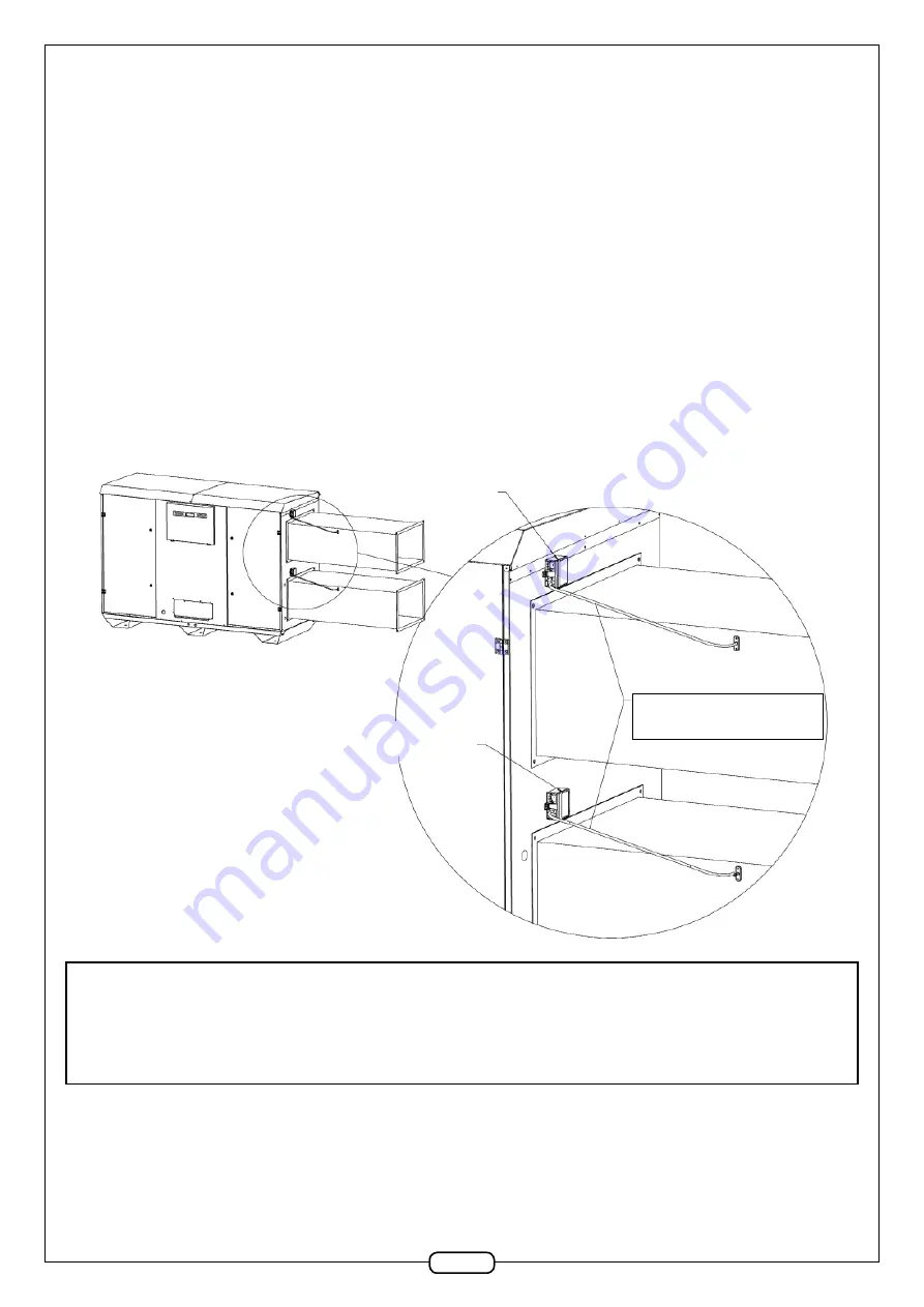
2.7.5 Constant pressure option
The kit consists of three RJ12 cables (labelled R8, R9 and R10) connected to the two PTH pressure sensors. Each sensor is linked to two metres of
transparent fl exible tube which is connected to 1 black pressure outlet. 4 self-tapping screws are provided in a plastic bag. The assembly is wired up
and constructed in the Factory and placed on the air input and output sidewall. Only the black pressure outlets are to be installed in ducts.
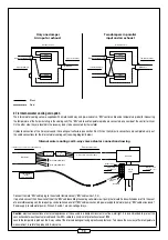
The upper PTH sensor should measure the pressure difference between the air outlet and the ambient air outside the unit. Its address arrow is set at
position “6”. The transparent hose is connected to the «-» sensor terminal (depressurised duct). Leave the «+» terminal exposed to fresh air. Drill a
10mm Ø hole in the outlet duct in order to insert the pressure outlet. Secure the pressure outlet, using two self-tapping screws. Remember to carefully
seal around each pressure outlet.
The lower PTH sensor should measure the pressure difference between the air inlet and the ambient air outside the unit. Its address arrow is set at
position “5”. The transparent hose is connected to the «+» sensor terminal (pressurised duct). Leave the «-» terminal exposed to fresh air. Drill a 10mm
Ø hole in the outlet duct in order to insert the pressure outlet. Secure the pressure outlet, using two self-tapping screws. Remember to carefully seal
around each pressure outlet.
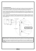
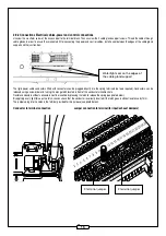
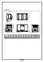
DETAIL D
SCALE 1 : 5
Outlet sensor address arrow
is set at position 6.
Inlet sensor address arrow
is set at position 5.
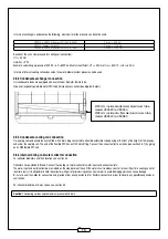
Flexible Transparent hose slopes
towards the black pressure outlet
No low point!
Warning:
the transparent tube must descend from the PTH pressure sensor to the duct’s black pressure inlet without allowing a low point beneath it.
Under certain conditions the air in the hose could condense. Water stagnation in the hose causes incorrect measurement leading to poor unit control!
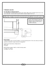
Warning:
for the best results, pressure should be measured where there is less risk of turbulence, that is to say, on a straight length of duct. The mini-
mum distance to be maintained from any turbulence is at least twice the diagonal of a rectangular cross section, and at least twice the diameter of a
circular section.


