


17
17
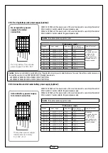
2.9.4 De-icing battery pack power supply (optional)
VEX520 à VEX550 unit: We recommend a 20A circuit breaker with a sensitivity differential of
300mA and 4mm2 section cable for the general power supply.
VEX560 à VEX580 unit: We recommend a 40A circuit breaker with a sensitivity differential of
300mA and 6mm2 section cable for the general power supply.
Caution:
three-phase power supply for all sizes.
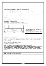
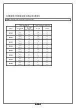
Battery power supply
Models
Power supply
Frequency
Max. power
consumption (W)
Type of terminal
VEX520
3 ~ N +T
50Hz
2620
Snap-lock
connector terminal
- cable section
0.5 to 10 mm² -
rigid conductor or
crimped contacts
recommended
VEX525
3 ~ N +T
50Hz
3740
VEX530
3 ~ N +T
50Hz
5610
VEX540
3 ~ N +T
50Hz
7480
VEX550
3 ~ N +T
50Hz
11220
VEX560
3 ~ N +T
50Hz
14960
VEX570
3 ~ N +T
50Hz
18700
VEX580
3 ~ N +T
50Hz
22440
Caution:
Each coil is controlled by a solid state relay. The solid state relay may cause radio interference. The use of mains fi lters can be necessary in
the event the user has to meet CEM (EN/IEC 55011 Standard) requirements.
- Unit VEX520 à VEX550 (XH1000 to XH3500):220nF/760V/X1 fi lter
- Unit VEX560 à VEX580 (XH4500 to XH7000):330nF/760V/X1 fi lter
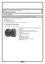
2.9.5 Connection electric heater battery power supply (optional)
VEX520 à VEX550 unit: We recommend a 20A circuit breaker with a sensitivity differential of
300mA and 4mm2 section cable for the general power supply.
VEX560 à VEX580 unit: We recommend a 40A circuit breaker with a sensitivity differential of
300mA and 6mm2 section cable for the general power supply.
Caution:
three-phase power supply for all sizes.
Battery power supply
Models
Power supply
Frequency
Max. power
consumption (W)
Type of terminal
VEX520
3 ~ N +T
50Hz
2620
Snap-lock
connector terminal
- cable section
0.5 to 10 mm² -
rigid conductor or
crimped contacts
recommended
VEX525
3 ~ N +T
50Hz
3740
VEX530
3 ~ N +T
50Hz
5610
VEX540
3 ~ N +T
50Hz
7480
VEX550
3 ~ N +T
50Hz
11220
VEX560
3 ~ N +T
50Hz
14960
VEX570
3 ~ N +T
50Hz
18700
VEX580
3 ~ N +T
50Hz
22440
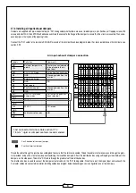
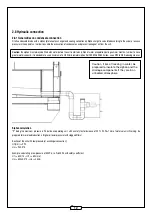
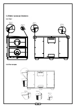
Internal battery power supply
to terminal connection
Three phase power supply
internal electric battery
3 x 400V +N +T
N
L1
L2
L3
A9T
A9L3
A9L2
A9L1
A9N
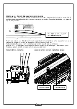
De-icing battery power
supply to terminal
connection
De-icing battery three phase
power supply N+T
N
L1
L2
L3
A7T
A7L3
A7L2
A7L1
A7N


