27
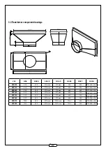
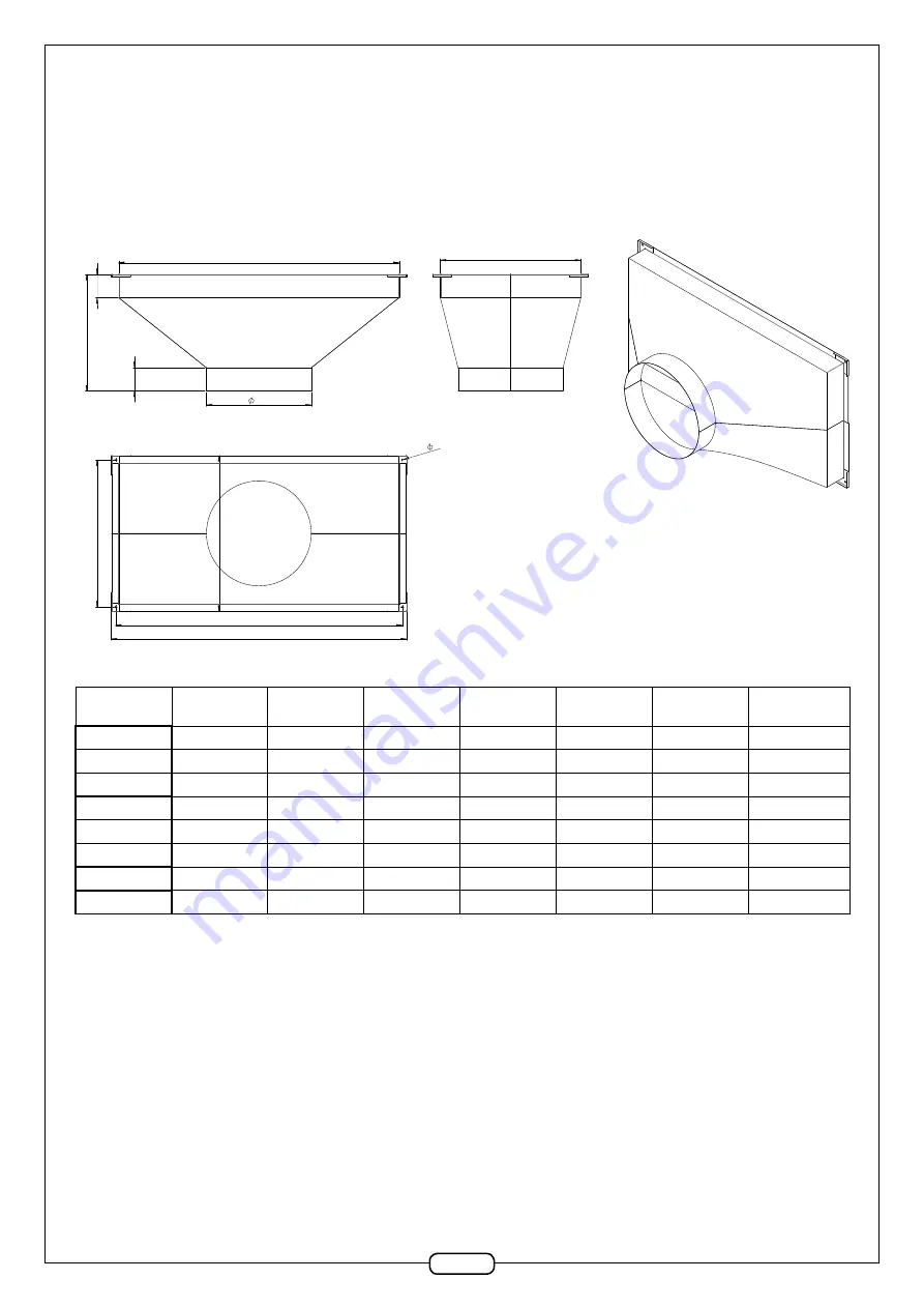
3.3 Transformer component drawings
FRWH(LQW
*LQW
FRWH)LQW
%
&
$
'
;+
&27($
&27(%
&27(&
&27('
&27((
&27()
&27(*
PD[
PD[
PD[
PD[
PD[
PD[
PD[
PD[
PD[
PD[
PD[
PD[
PD[
PD[
PD[
PD[
VEX
SIDE
SIDE B
SIDE C
SIDE D
SIDE E
SIDE F
SIDE G
VEX520
430
330
370 max
470 max
384
284
Ø
313.85
±
0.45
VEX525
530
330
370 max
570 max
484
284
Ø
353.8
±
0.5
VEX530
730
330
370 max
770 max
684
284
Ø
353.8
±
0.5
VEX540
630
430
470 max
670 max
584
384
Ø
498.75
±
0.55
VEX550
930
430
470 max
970 max
884
384
Ø
498.75
±
0.55
VEX560
930
530
570 max
970 max
884
484
Ø
628.8
±
0.6
VEX570
1230
530
570 max
1270 max
1184
484
Ø
628.8
±
0.6
VEX580
1430
530
570 max
1470 max
1384
484
Ø
708.65
±
0.65

