background image

8

8

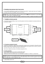
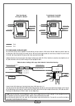
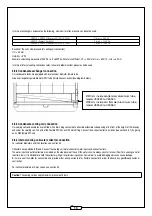
2.6 Installing the temperature probe (air input sensor)

The air input temperature probe is delivered connected to the control terminal, terminals M16-M17. It must be located in the input duct. The probe must 
pass through the connection terminal cable gland in order to ensure an IP54 seal. 

Important:

 When the system includes heating or cooling coils, the probe must be placed after these heat components at a minimum distance of 

1.5 metres – in order to ensure an even temperature on the section.
In terms of the duct, the probe, passes through a PG 9 cable gland, ensuring that the duct is sealed. It is maintained the entire length by a metal rod.

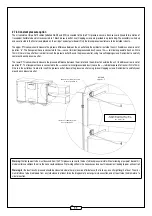
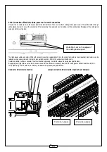
2.7 Installation options/accessories

The 2 side panels are equipped with M8 inserts at each corner of the opening frame in order to accommodate external accessories (transformer com-
ponents-dampers–Canopies).

Dampers

Transformer 
components 

Rain canopy

2.7.1 Transformer component connection 

Provide M8 screws and a EPDM foam self adhesive seal for installing transformer components on the unit. Glue the seal on the fl ange of the transformer 
component to ensure that the structure is sealed. Then screw each transformer component into the inserts of the frame. To connect the circular ducts, 
these must be fi tted with a rubber O-ring. See diameters per machine in Section 3.3.

Insulate ducts and shaped parts in accordance with the Standards and regulations in force.

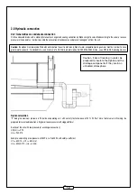
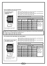
2.7.2 Canopy installation 

Canopies are supplied with M8 screws and a 5x10mm thick EPDM self adhesive seal.
Glue the seal onto the fl ange of the canopy to ensure that the structure is sealed.
Canopies help protect the unit from rainwater intrusion. They can be attached to the opening frame, on a damper or a rectangular sleeve.

Caution:

 To prevent the recirculation of exhausted air towards the the fresh air, allow a minimum distance of 4m between the air input and exhaust outlet

(See for DTU 68-3 section 1-1-4 residential buildings). For commercial buildings the RSDT requires that «the exhaust air extracted from the rooms must 
be ejected at least eight metres from any window or fresh air input».

For canopy dimensions see section 3.2.2

Summary of Contents for Everest XH

Page 1: ...VEX500 Everest XH Installation instructions EN www aldes com...

Page 2: ...2 7 3 Installing air input exhaust dampers 9 2 7 4 Internal water cooling coil option 10 2 7 5 Constant pressure option 11 2 7 6 LON option 12 2 8 Hydraulic connection 12 2 8 1 Generalities on condens...

Page 3: ...520 525 530 23 3 1 2 VEX540 550 24 3 1 3 VEX560 570 580 25 3 2 Exterior accessory dimensions 26 3 2 1 Roof 26 3 2 2 Rain canopies 26 3 3 Transformer component drawings 27 3 4 Diameter of internal wate...

Page 4: ...s are defined in sections 2 9 3 2 9 4 and 2 9 5 of the installation manual The product must be powered down before any maintenance or cleaning operation Make sure that the unit cannot be accidentally...

Page 5: ...ply Single phase 230VAC to VEX520 VEX580 Three phase 400VAC N T for the others Battery power supply Three phase 400VAC N T Side panel 2 opening frames Side panel 2 opening frames Access door to intern...

Page 6: ...unit Place the sling loops around the lifting bars and place spacers above the unit so as not to damage the casing See Diagram below Separators Sings Lifting bars 2 3 Parts included in the package 2 3...

Page 7: ...to drain the condensates from the exchanger and cooling coil See section 2 8 1 700 700 2 4 2 Exterior version The Everest units have IPX4 protection against water damage and pitting units destined fo...

Page 8: ...lf adhesive seal for installing transformer components on the unit Glue the seal on the flange of the transformer component to ensure that the structure is sealed Then screw each transformer component...

Page 9: ...GND RG1 ON OFF insulation damper relay NO active if option has been selected RG2 24 24V AC actuator damper GND 24 24V AC CO2 probe GND M36 unit Alarm return relay NO M37 2 or 3 horizontal terminal ju...

Page 10: ...tor connection drawing Towards unit connection terminal block BW Cable Temperature probe on 3 way valve Heat pump ON OFF Connector male 3 pin Connector female 3 pin 3 way valve actuator cable Towards...

Page 11: ...n the air inlet and the ambient air outside the unit Its address arrow is set at position 5 The transparent hose is connected to the sensor terminal pressurised duct Leave the terminal exposed to fres...

Page 12: ...pacity it is advisable to use a minimum of a 32mm diameter siphon for VEX520 525 530 sizes use a 20 to 32 reducing sleeve Caution if risk of freezing in winter be prepared to insulate the siphon and t...

Page 13: ...densate tanks are fitted with a drain plug connected to a flexible extensible tube opening at the front at the height of the raceway and under the cooling coil The end of the flexible PVC has an 32 ma...

Page 14: ...l Power The unit has an electric mains power circuit and a electric battery circuit Each circuit has its own built in control switch in a compartment located behind the black door at the top of the un...

Page 15: ...th connectors can be plugged directly into the spring terminals no tools required Conductors can be released using a screwdriver and turning the orange latch located in front of the conductor s insert...

Page 16: ...r terminal cable section 0 14 to 4 mm rigid conductor or crimped contacts recommended VEX525 1 230VAC T 50Hz 1000 VEX530 1 230VAC T 50Hz 1000 VEX540 1 230VAC T 50Hz 1420 VEX550 1 230VAC T 50Hz 2720 VE...

Page 17: ...ents Unit VEX520 VEX550 XH1000 to XH3500 220nF 760V X1 filter Unit VEX560 VEX580 XH4500 to XH7000 330nF 760V X1 filter 2 9 5 Connection electric heater battery power supply optional VEX520 VEX550 unit...

Page 18: ...ECO 450 Pa max HE F7 filters 250 Pa ECO 450 Pa max Consult the parameters notice for resetting the load loss when changing filters in dynamic alarm 2 11 Configuring TCP IP communication Connect the RJ...

Page 19: ...IP address and DNS server address Depending on the version of Windows these are the 2 access paths a With Windows XP Start Connections Show All Connections Right click local area connection properties...

Page 20: ...20 b With Windows 7 Control Panel Network and Internet Network and Sharing Centre Local network connection Properties Click on Internet Protocol Version 4 Properties...

Page 21: ...IP address 172 20 20 4 Subnet Mask Identical Subnet mask to that of the PLC 255 255 255 0 identical to the PLC 3 Open a web page with Internet Explorer and enter the PLC s IP address The following pag...

Page 22: ...SC Turn the knurled knob to navigate through a menu Press on the knurled knob to select a menu Press ESC to exit a menu 2 12 2 Menu access To access User level no password is required To access Instal...

Page 23: ...3 3 3 3 3 e7 3RVLWLRQ FROOHFWHXUV EDWWHULH P1 P2 P3 P4 P5 P6 P7 P8 P9 P10 Weight kg Volume m3 VEX520 589 416 561 430 430 66 262 285 75 75 205 1 25 VEX525 714 541 686 484 530 78 262 285 78 78 239 1 51...

Page 24: ...eight kg Volume m3 VEX540 913 742 886 584 630 128 361 287 87 77 366 2 85 VEX550 1292 1121 1265 884 930 168 398 269 110 88 494 4 04 SLTXDJH SLTXDJH 3 3 3 3 0 0 3 3 0 0 3 3 3 3 3 3 e7 3RVLWLRQ FROOHFWHX...

Page 25: ...EDWWHULH DETAIL A Cooling coil collector location L1 P1 P2 P3 P4 P5 P6 P7 P8 P9 P10 Weight kg Volume m3 VEX560 2503 1271 1106 1244 884 930 157 558 262 95 85 554 5 39 VEX570 2503 1271 1384 1522 1184 12...

Page 26: ...26 3 2 Exterior accessory dimensions 3 2 1 Roof 3 2 2 Rain canopies DETAIL A SCALE 1 3 DETAIL B SCALE 1 3 DETAIL C SCALE 1 5 DETAIL D SCALE 1 5 DETAIL A DETAIL B DETAIL C...

Page 27: ...0 370 max 470 max 384 284 313 85 0 45 VEX525 530 330 370 max 570 max 484 284 353 8 0 5 VEX530 730 330 370 max 770 max 684 284 353 8 0 5 VEX540 630 430 470 max 670 max 584 384 498 75 0 55 VEX550 930 43...

Page 28: ...ling coil Ext copper collector Inch GAS thread Kvs valve DN mm VEX520 1 row 1 2 0 63 15 2 rows 1 2 1 6 15 VEX525 1 row 1 2 0 63 15 2 rows 1 2 2 5 15 VEX530 1 row 3 4 1 6 15 2 rows 3 4 4 20 VEX540 1 ro...

Page 29: ...iven time period software parameter to be set Connect M4 M3 to set up High speed Fire Alarm Contact triggers forced ventilation at a given speed software parameter to be set Connect M8 M7 for fire ala...

Page 30: ...30 NOTE...

Page 31: ...31...

Page 32: ...www aldes com 110 68 644 A 06 2018 RCS 956 506 828 IPrinted in France...

Reviews: