9
9
2.7.3 Installing air input/exhaust dampers
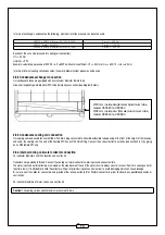
Dampers are supplied with pre-wired actuators, an "RG" linking cable (whether there are one or two dampers), a junction box, self tapping screws, M8
screws and a 5x10mm thick EPDM self adhesive seal. Glue the seal onto the fl ange of the damper to ensure that the structure is sealed. Then screw
each damper in the inserts of the opening frame.
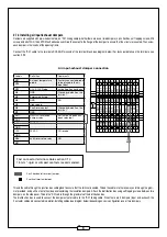
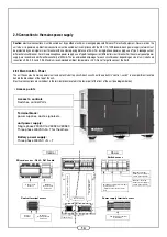
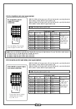
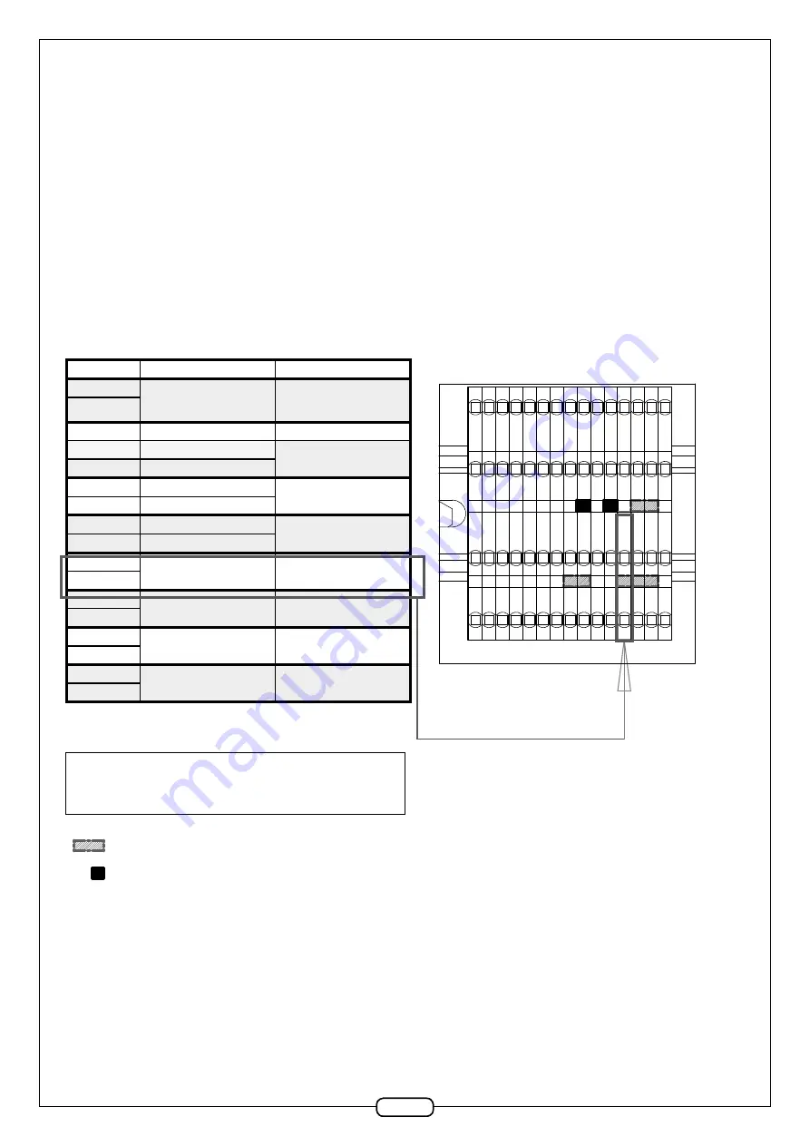
Connect the "RG" cable to the terminals RG1-RG2 terminals of the terminal block (see diagram below). For technical details on the terminals, see
section 2.9.2
Air input-exhaust damper connection
Labels
Defi nition
Comments
M17
Air input temperature
probe
Factory connected probe
to be placed in the air
input duct
M16
M12
CO
2
-0-10V Probe
active if option has been
M4
GND
Closed by default on the
terminal
M5
External unit stop
M4
GND
NO
M3
High speed
M8
Fire Alarm contact
Closed by default on the
terminal
M7
GND
RG1
ON/OFF- insulation
damper relay
NO (active if option has
been selected)
RG2
+24
24V AC
actuator damper
GND
+24
24V AC
CO
2
probe
GND
M36
unit Alarm return relay
NO
M37
2 or 3 horizontal terminal jumper
2 vertical terminal jumper
Fast connector terminal-cable section 0.14
1.5mm
2
-rigid or crimped contacts recommended.
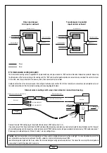
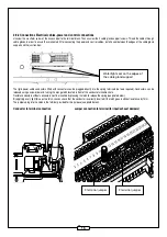
Thread the cable through the junction box cable gland to ensure that the terminal is sealed. Thread the cable into the raceway, and through the grom-
met provided, and pull it out onto the side panel containing the insulation dampers. Attach the distribution box using self tapping screws between two
dampers, on the side panel. Thread the "RG" cable through the grommets of the distribution box.
The distribution box is used to connect the damper actuator cable to the "RG" linking cable. When there are 2 dampers (input and exhaust), the
2 actuator cables are connected in parallel. Installing cables (see diagram below) depending on your confi guration-one or two dampers.
0 0
$,
*1'
0
5*
0
0
$,
$,
$5
$5
$5
$5 $5 $, $, $,
0 5* *1'
0
0
0
$5
7YHU
0
0 0
*1'
0
0 0
0
0
0
5*
0
0 0 7MDX
0
0
0
0
0
0
0
0
0
0
0
0
0
0
0

