11
Caution:
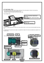
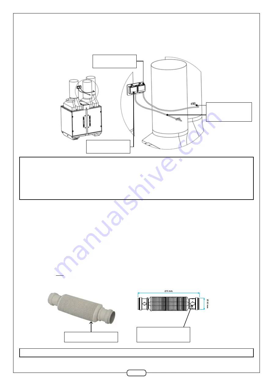
the transparent tubes must descend from the pressure inlet of the PTH sensor to the black pressure inlet on the duct without a low bend
that may cause a water trap. Under certain conditions, the air in the tube may condensate. Water stagnating in the tube would cause incorrect
measurements and therefore incorrect control of the unit!
Caution:
to obtain the best possible results, the pressure must be measured where there is least risk of turbulence, i.e. on a straight section of duct.
The minimum distance to respect from any source of perturbation is at least twice the diagonal of a rectangular cross-section and at at least twice the
diameter of a circular cross-section.
2.6.7 LON option
The kit contains 2 x RJ12 cables, a, RJ12 split (2 female inputs
→
1 female output) and an OJ Air2 LON module. The whole kit is factory pre-wired and
connected to the connection terminal block.
Connect the RJ12 cable labelled R11 waiting on the spar to one of the two female RJ12 connectors on the LON module.
The LonWorks networks cable is connected to the OJ Air2 LON module via the PTR 2-point connector on the module.
2.7 Hydraulic connection
2.7.1 Connecting condensate drains - general
All condensate drains must be connected to a water trap (plate heat exchanger and cooling coil optional). The water traps are delivered with each unit,
in a box placed inside the unit. The membrane water traps are used to eliminate the negative pressure in the device, so as to enable the drainage of
condensate or to prevent an air leak from the unit.
NB:
to prevent the risk of freezing in winter, insulate the water trap and the drain accessories if they are located in a non-heated area!
Membrane water trap
Condensate drain
direction
Exhaust sensors
Address pointer on 6
Sloping transparent hose
to black pressure inlet
No low bends!
Air supply sensor
Address pointer on 5

