13
2.8.1 Control principle - Power
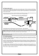
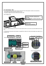
Each unit has an electrical control box on its roof. This box contains the power and control components, and features two access hatches:
- One screwed hatch for the electrical connections (power and control)
- One quarter-turn locking hatch for access to the PLC and switch connections
Refer to the diagram below.
The Unit has a general power supply circuit and one circuit for each electrical coil. Each circuit has its own switch located behind the quick access
hatch.
The terminal blocks for the power and control components are separated by the transformer. The transformer is protected by fuses upstream (1 A) and
downstream (2.5 A).
Access to connection terminal block
(screwed)
Power supply (mains + electrical coil), sensor,
control options
Quick access
PLC and switch connections
Access to control terminal blocks
Access to power terminal blocks
Power
Control system
Access to SD card - RJ45 cable - RJ12
Access to switch
Optional terminal blocks
for coils
Power fuse
Power terminal block
Power supply -
distribution
Control terminal block
Control fuses
Optional:
Extension control power supply
Control terminal block
Transformer
Connection box
Optional: Frost-
protection coil power
switch (400 V 3-phase)
Optional: Internal
electric coil power
switch
(400 V 3-phase)
Unit power supply switch
(single or 3-phase)
Master control PLC

