5
2.1 General
Attention:
the purpose of this document is to provide instructions on the installation of the unit. To ensure the installation is fully compliant, refer to
applicable legislation in effect in the country of installation (e.g. NF DTU 68-3 part 1.1.4).
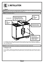
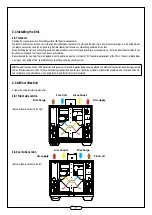
• Access points
Access door to
internal components,
protected with an 8
mm Hex cap key
Top:
2 opening
frames
Quick access hatch
to PCB and switches
Screw-fit access hatch
Terminal block for power
supply and control system
The unit identification plate is provided in duplicate. One plate is located on the back of the quick access hatch and another is on the side panel.
The unit is packaged in plastic film, protected with cardboard corner pieces. All accessories ordered with the unit are delivered unassembled. Refer to
section 2.6 for fitting accessories.
Attention:
do not drill the panel between the two access doors, nor the base plates as they support the cable bundles!
2.2 Transport on site
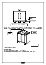
The unit is mounted on cross-pieces. When transporting using a forklift, ensure that the forks are long enough for all the spars to rest on them. En-
sure that the cross-pieces are not damaged when the forks are passed under the unit (ensure minimum clearance of 350 mm for the XV1600 and the
XV2300).
2. INSTALLATION
Top:
2 opening
frames
Caution:
the unit is designed for indoor use.

