background image

Inspir

AIR™ Home Standard Residential HRV/ERV

7

5.  When cutting or drilling into wall or ceiling structures, do not damage electrical wiring 

or other hidden utilities.

6.  Do not use this unit with any speed controls, dehumidistats or timers other than those 

specifically indicated within this manual. 

7.  This unit must be grounded. The power supply cord has a three-prong grounding 

plug for your personal safety. It must be plugged into a mating 3-prong grounding 

receptacle, grounded in accordance with national and local codes.  Do not remove the 

ground prong. Do not use an extension cord.

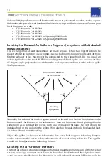
8.  Do not install exhaust grilles in a cooking area


(see “Locating the Exhaust Air Grilles or 

Registers” on

 page 14).

 Do not connect directly to any appliances.

9.  Do not use to exhaust hazardous or explosive materials and vapors.

10.  When performing installation, servicing or cleaning the unit, it is recommended to wear 

safety glasses and gloves.

11.  When local regulations comprise more restrictive installation or certification 

requirements, such requirements supersede those in these instructions.

CAUTION

1.  This unit is intended for residential use only, conforming to the requirements of the 

International Residential, Building, and Mechanical Codes, NFPA 90B for the United 

States and the National Building Code of Canada.

2.  Turn the unit off during construction to avoid clogging the filters and loading the 

blowers with construction dust.

3.  Refer to the specification sheet for the specific model’s  dimensions, electrical 

requirements, drain connections, etc.

4.  Ducting of stale air to the outdoors and fresh air from outdoors, must be terminated 

outdoors, not attics, crawl spaces, or attached garage.

Ducting Configurations

The interior ducting system’s purpose is to remove stale air and circulate fresh air to all 

habitable rooms. It is the responsibility of the installer to ensure all ductwork is sized and 

installed as designed to ensure the system will perform as intended. 

The amount of air (CFM) that an HRV/ERV will deliver is directly related to the total external 

static pressure (ESP) of the system. Static pressure is a measure of resistance imposed on the 

blower by a length of ductwork plus the number of fittings used in the ductwork.

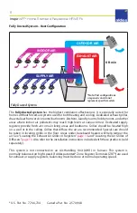
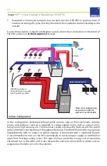
The following pages outline 4 duct configurations, from most desirable to least desirable.

Note:  These configurations are intended for typical single-family and multi-family residences. 

Applications such as greenhouses, atriums, swimming pools, saunas, etc., have unique 

ventilation requirements that should be addressed with an isolated ventilation system.

Summary of Contents for InspirAIR E110-TF

Page 1: ...Y VENTILATORS FOR MODELS H95 TRG H110 TF H150 TRG H190 TRG E110 TF E150 TRG E190 TRG Installing Contractor Telephone Contact Serial Number Installation Date TO BE COMPLETED BY CONTRACTOR AFTER INSTALL...

Page 2: ...nections HRV Models Interlocking the HRV ERV to an Air Handler Furnace Blower Unit Wiring Enabling Slave Mode Using Slave Mode Field Wiring Electrical Interface Installing the Digital Multifunction Co...

Page 3: ...or support on older models not shown in this table please contact 1 800 255 7749 This product earned the ENERGY STAR by meeting strict energy efficiency guidelines set by Natural Resources Canada and...

Page 4: ...ss humid air stream How Heat Energy Recovery Ventilators Work In the heating season InspirAIR Home Heat Recovery Ventilators HRV and Energy Recovery Ventilators ERV draw in fresh air from outside This...

Page 5: ...l depend upon Number of occupants and their activity levels How your home was built Your personal preferences for fresh air The InspirAIR Home HRV ERV introduces fresh air to your home while recoverin...

Page 6: ...this system will operate if connected to any other piece of mechanical equipment that operates at a higher static i e a force air furnace or air handler After installation the compatibility of the two...

Page 7: ...nal Residential Building and Mechanical Codes NFPA 90B for the United States and the National Building Code of Canada 2 Turn the unit off during construction to avoid clogging the filters and loading...

Page 8: ...re recommended Special care should be taken in locating grilles in the floor Areas under baseboard heaters will help temper the air See Locating the Exhaust Air Grilles or Registers page 14 and Locati...

Page 9: ...n this case the AHU must run continuously or be interlocked to operate with the HRV ERV to avoid loss of balanced supply and exhaust airflows 2 In multi speed AHU s balancing must be conducted on the...

Page 10: ...ir system will draw the fresh air into the return grilles of the AHU and distribute it throughout the house The HRV ERV and AHU may operate independently with no impact on airflow balance A thermostat...

Page 11: ...The balance of supply and exhaust airflows can change from the AHU turning on and off or operating at different speeds for heating and cooling cycles It is recommended that this configuration should...

Page 12: ...ise passing the ducting to interior spaces Connecting the Ducts For the air exchanger to run optimally place the ducts so they are as straight as possible Ducts should be kept short and have as few be...

Page 13: ...457 mm above the ground or above the depth of expected snow accumulation At least 3 feet 1 m from the corner of the building Do not locate in a garage attic or crawl space Exhaust Air Wall hoods At le...

Page 14: ...ed outwards from the cooking element closest to the exhaust grille See figure below 45 45 Cooking Equipment Floor Do not install above or inside this area Normally the exhaust air intake register woul...

Page 15: ...systems the ZRT 1 model provides on off control for on demand ventilation The optional Constant Airflow Regulator CAR II or MR Modulo can be installed in the ZRT 1 s extended duct collar to place a m...

Page 16: ...controls with a dehumidistat function that will achieve further dehumidification from the HRV ERV High speed ventilation will be initiated upon exceeding the dehumidistat setpoint Once the humidity i...

Page 17: ...ply and exhaust Exterior wall hoods for supply and exhaust P N 22 304 P N 22 305 P N 22 306 P N 22 025 or P N 22 026 Insulated duct Uninsulated duct MR Modulo P N 11016308 P N 11016309 P N 11016310 or...

Page 18: ...g to seal each spout to the pan Hand tighten the washer and lock nut that holds the drain spout in place Construct a P Trap using the plastic tee connector Cut two lengths of drain hose and connect th...

Page 19: ...s Manual Wiring Diagram for instructions on connecting to the fan start relay Note It is the same process as connecting the fan control on a thermostat 2 Ensure the air handler furnace blower motor is...

Page 20: ...ll need to be placed into slave mode Note While in slave mode the recirculation function is replaced by defaulting to the standby or OFF condition Aldes controllers which have this function will conti...

Page 21: ...screwdriver remove the three screws that secure the metal control board cover Removing the screws 4 With the cover removed locate the jumper pins on the control board These are positioned just behind...

Page 22: ...nstalling the circuit board cover followed by the terminal block The unit is now in Slave mode and can be installed Using Slave Mode When the unit is in slave mode there are three modes of operation a...

Page 23: ...MAX provides demand based high speed operation for maximum ventilation This disables frost control and should only be used for short periods of time such as boosting ventilation for bathroom exhaust T...

Page 24: ...rols the relative humidity rate Equipped with a high accuracy fast response humidity sensor and an electronic system it efficiently controls your air exchanger to keep the humidity rate in your home b...

Page 25: ...TRG H E190 TRG Electronic HRV ERV Models H95 TRG H E110 TF H E150 TRG H E190 TRG Without Recirculation Models H E110 TF Relay HRV ERV Models None Connect each wire to the terminal board on the back of...

Page 26: ...e Aldes 611228 timer unit high speed air is exchanged during its countdown interval Automatically controls the level of relative humidity by activating the high speed air exchange when the humidity le...

Page 27: ...gned for the device s default mode e g when the humidity rate drops below the recommended level OPTION 1 OPTION 2 OPTION 3 Units WITH and WITHOUT recirculation To set the device s default settings to...

Page 28: ...speed 20 min exchange 40 min stop mode or recirculation Low speed exterior exchange mode High speed exterior exchange mode Stop mode or recirculation indicator lights are off Mode Control P N 611230 T...

Page 29: ...ce the damper is opened the ZRT signals the HRV or ERV to boost speed and airflow from the open ZRT making it ideal for residential bathroom ventilation Aldes VentZone Zoned IAQ with Heat and Energy R...

Page 30: ...minal to the Ventilator VentZone kits provided with 24V ZRTs are designed to be powered completely through the ventilator Use of the 20 40 60 Minute Timer P N 611228 is recommended to prevent over ven...

Page 31: ...e it may condense in cold weather and degrade structure components It may also cause key holes to freeze up Excessive negative pressure may have several undesirable effects In some geographic location...

Page 32: ...includes zone dampers or Zoned Register Terminals ZRT it must be balanced at a speed lower than normal operation If balanced at high speed the HRV ERV will not be in balance at the lower speeds due t...

Page 33: ...n a slight positive pressure is desired to help resist backdraft from combustion devices radon gas or drawing air from an attached garage Balancing Airflow and Adjusting Motor Speed FLEXControl User I...

Page 34: ...ed level 2 Adjust the EXHAUST FAN OUT air stream Connect the tubes like the diagram below shows then turn the FAN OUT potentiometer to the desired level Supply Airstream Connections Exhaust Airstream...

Page 35: ...he area to obtain airflow Applicable models You would use this method with higher efficiency filters There are three in duct balancing methods 1 Pitot tube and manometer or digital differential pressu...

Page 36: ...the airflow rate roatet the dial The airflow indicator will move to show the selected CFM These rates can be changed at any time after installation is complete but rebalancing may be required Balanci...

Page 37: ...just the speed to be just above the point where the pressure starts to drop off 11 Record this pressure measurement 12 Refer to the reference chart on the unit that shows the pressure readings versus...

Page 38: ...grease USE Trap impurities and pollen use on supply side only CARE Replace each season CARE Replace spring and fall CARE Clean 2 3 times year with water and mild detergent CARE Replace each season ME...

Page 39: ...USE WATER DO NOT USE PRODUCTS CONTAINING SOLVENTS DO NOT USE HOUSEHOLD CLEANING PRODUCTS c Wipe the interior with a dry cloth 8 Fans No maintenance needed After Performing Maintenance Slide the core...

Page 40: ...tion by the Seller does not disclose any defect in material or workmanship the Seller s regular charges will apply This warranty shall be effective only if use and maintenance is in accordance with ou...

Page 41: ...esidential HRV ERV 41 American ALDES Ventilation Corporation 4521 19th St Ct E Suite 104 Bradenton FL 34203 1 800 255 7749 www aldes us Aldes Canada 100 Rue Carter Saint Leonard d Aston QC J0C 1M0 1 8...

Page 42: ...spirAIR Home Standard Residential HRV ERV 42 Date of Purchase ______________________________ Retailer ______________________________________ Keep receipt as proof of purchase MAINTENANCE PERFORMED DAT...

Page 43: ...InspirAIR Home Standard Residential HRV ERV 43...

Page 44: ...le or in part of this document in any form or by any means without the express written consent of American ALDES Ventilation Corporation is strictly prohibited The information contained within this do...

Reviews: