5
1.
The supply voltage is 230 VAC / 50 Hz.
2.
The electrical connections will be
made as per the rules of French standards
NF C 15-100.
In particular :
- The motor must be protected in the
fixed installation by an omnipolar device
with 3 mm opening gap per contact.
- The supply cable section must be at
least 0.75 mm
2
per conductor.
- The supply cables must not be lighter
than H05 VV-F or H05 RR-F.
3.
We also recommend to use of a magne-
to-thermic circuit breaker.
0,4 to 0,6 A - code 56.183.
CAUTION
:
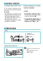
• Do not forget to connect the earth
to
the terminal strip at the position indica-
ted by the earth symbol .
• If connecting the thermo-contact, to
retain the C4 classification (collective
housing use), use cabling
➀
only.
■
ELECTRICAL CONNECTION
CABLING
PRESSURE SWITCH CONNECTION
■
WIRING DIAGRAMS
blue
blue
black
ON
OFF
brown
supply
Pressure switch
brown
black
R
M
orange
orange
black
white
green/yellow
TC
CABLING OF
THERMO-CONTACT
signalling
or
bro
wn
ye
llo
w
c
: relay which can be operated by the pressure
switch.
Pressure switch break power at 250 V
- Resistive : 5 A max.
- Inductive : 3 A max.
R


