15
2.9. Connection to the electrical supply
Caution:
electrical connections must be made by a qualified electrician, wearing the appropriate Personal Protection Equipment. Never work on a
live unit. The electrical connection will be in compliance with NF-C 15-100. Each supply network must be protected by an omnipolar circuit breaker
with an opening distance of 3 mm per contact. For a single-phase supply, used a leak current differential circuit breaker type A. For a three-phase
supply use a leak current differential circuit breaker type B. We recommended a sensitivity of 300 mA for the differential for both these types of
supply. The amperage draw recommended for each circuit breaker, according to the sizes of units, is defined in Sections 2.9.3 and 2.9.4. Maximum
recommended ambient temperature < 45°C. Do not forget to connect the earth.
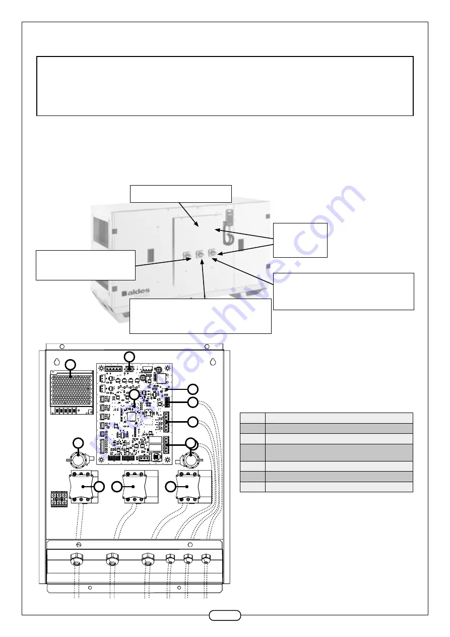
2.9.1. Control - Power principle
Every unit has an electrical connection box on the front panel. This box gives access to the electrical power and control components (disconnect
switches, cut-off supply, electronic control board, etc.). The unit has a general supply electrical circuit and, depending on the options, an electrical coil
circuit (defrosting and heating).
The electrical components are accessed via a hatch equipped with hexagonal recessed head screws M6.
Electrical connection box
4x Torx t30
screws M6
Unit power supply switch:
Single-phase 230 VAC + E
Heating coil power supply:
VEX410 : Three-phase VAC + E
VEX420 to 440: Three-phase VAC + N + E
Defrosting coil power supply: VEX410 :
Three-phase VAC + E
VEX420 to 440: Three-phase VAC + N + E
No.
Description
A
Power supply 230 VAC> 24 Dc
B
Control board
C
Pressure sensor:
constant airflow or constant pressure option
D
General disconnect switch
E
Defrosting coil disconnect switch
F
Post-heating coil disconnect switch
A
B
C
D
E
H
G
F
A
B
C
C
F
E
D


