READ AND SAVE THESE INSTRUCTIONS
ZRT-PDIL / ZRT-PDIL-HP
AIRFLOW & ZONE CONTROL
PARALLEL DAMPER IN-LINE ZONE TERMINAL
IOM
*U.S. Pat. No. 9,759,442
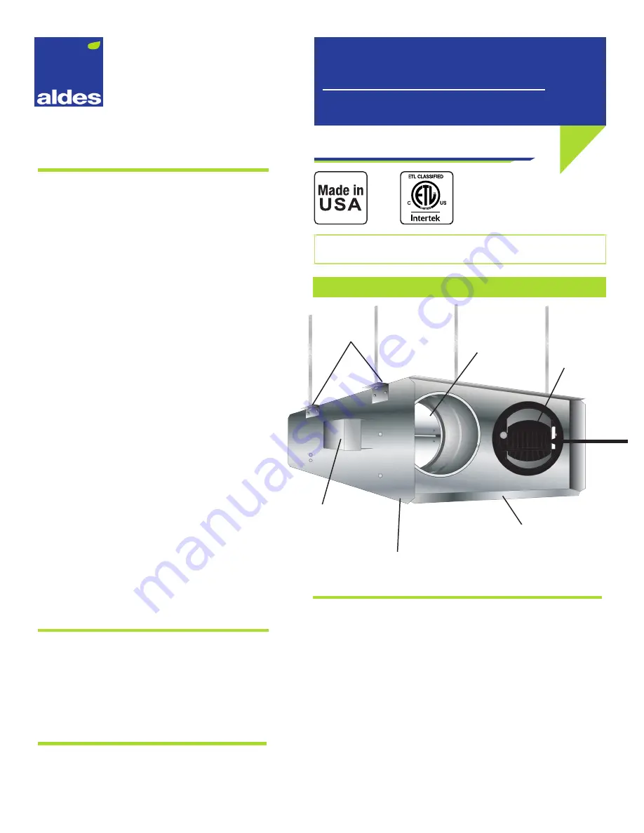
FIGURE 1 - MOUNTING
Integral
Continuous CAR
Flanges for attaching to
rectangular duct in a slip-type
duct connection
Power Connection
(24 VAC or 120 VAC)
to Motorized Damper
Motorized Damper
and Boost CAR
Screw-On Access Plate
Hanging Brackets
AIRFLOW
Description
Aldes Parallel Damper In-Line Zone Terminals
(ZRT-PDIL) are designed to introduce flexibility
and dynamic control to central supply or exhaust
ventilation systems. Used in both large and small
systems, the ZRT-PDIL regulates ventilation without
the need for individual fans or traditional VAV
terminal units.
Each ZRT-PDIL is a two-position, pressure-
independent terminal with a control damper to
regulate high limit on-demand airflow control and
integral passive regulators for automatic air balancing
of the continuous and boost airflow setpoints.
This unique combination provides flexible control
schemes without the need for expensive pneumatic,
electronic, or DDC control systems.
The ZRT-PDIL is primarily used for combination low-
flow indoor air quality ventilation or make-up air, and
on demand high-flow spot ventilation using the same
central exhaust or supply fan system. This is achieved
by integrating a minimum Constant Airflow Regulator
(CAR) in the terminal end panel and in-line with the
branch duct. The maximum airflow is controlled by
a series of 24 VAC or 120 VAC powered motorized
damper(s) and a secondary CAR airflow controller.
With the maximum-air motorized control damper
completely closed, the continuous CAR allows steady,
low-volume airflow control. (Continuous and Boost
Constant Airflow Regulators may be CAR-II or CAR3
depending on required airflow. See ZRT-PDIL CFM
Range for details).
When other ZRT-PDIL are activated for on-demand
control of high flow, the unpowered ZRT-PDIL will
maintain the specified continuous rate through the
pressure-independent CAR. Opening the ZRT-PDIL’s
control damper adds its calibrated boost airflow rate
to the continuous setpoint.
Mounting
The ZRT-PDIL/ZRT-PDIL-HP is intended to be installed
in-line in a duct system. It is provided with four (4)
mounting tabs that are suitable to suspend the unit
with threaded rods (not included). See Figure 1. The
unit should be installed in a location that provides
clearance for the access plate.
Maintenance
All components of the ZRT-PDIL/ZRT-PDIL-HP are
accessible through the opening provided by the
access plate.
Wiring
ZRT-PDIL/ZRT-PDIL-HP wiring needs to meet all applicable electrical
and building codes. If the electrical connection to the damper
motor wiring box is not accessible after mounting, there needs to
be enough slack (approximately 24”) in the electrical wiring leading
to the wiring box to allow the damper assembly to be removed
through the access opening. This will allow access to the electrical
connections from the access opening.
ZRT-PDIL/ZRT-PDIL-HP models are available with 24 VAC or 120 VAC
motorized dampers. 120 VAC wiring is shown in Figure 2 and 24 VAC
wiring is shown in Figure 3 (next page).


