background image

28

29

2

L

13

23

F

5

A

B

C

G

50–300 mm

H

I

8

24

25

26

27

10

24
25

9

/

11

K

Summary of Contents for Deco Style DS-FSS 500

Page 1: ...PAINT SPRAY SYSTEM User Manual Original instructions ID 05007 m y hansecontrol c o m M A N U A L DEVELOPED IN G E R M A N Y User friendly Manual ...

Page 2: ...d spray unit 14 Adding material 15 Fitting changing the spray unit 16 Operation 17 Switching the paint spray system on and off 17 Adjusting the spray pattern 18 Controlling the flow of material 18 Setting the spraying width 19 Replacing the nozzle set 19 Application information 20 Maintenance and care 21 Cleaning the spray unit 21 Cleaning the motor unit 23 Changing the air filters 24 Storage 24 T...

Page 3: ...1 2 3 9 8 7 6 5 4 11 10 10 8 7 6 12 5 15 16 17 18 13 14 A 3 ...

Page 4: ...4 22 21 20 19 12 23 22 21 20 19 23 11 9 E 15 C 7 5 D 4 18 B ...

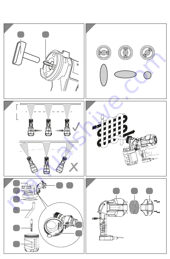
Page 5: ...28 29 2 L 13 23 F 5 A B C G 50 300 mm H I 8 24 25 26 27 10 24 25 9 11 K ...

Page 6: ...rial quantity control 1 per spray unit 22 Rotating cap 1 per spray unit 8 Paint container 1 per spray unit 23 Needle 1 per spray unit 9 Spray unit for interior wall paints 24 Ventilation tube multiple parts 10 Lid 1 per paint container 25 Suction tube 11 Spray unit for lacquers and glazes 26 Lid seal 1 per cover 12 Union nut with adjusting ring spray unit for lacquers and glazes 27 Container seal ...

Page 7: ...nce If you pass the paint spray system on to a third party please ensure that you include this user manual Explanation of symbols The following symbols and signal words are used in this user manual on the paint spray system and on the packaging WARNING Indicates a hazardous situation that may result in death or serious injury if not avoided CAUTION Designates a dangerous situation that may result ...

Page 8: ...accidentprevention occupational healthorsafety whichspecificallyand orgenerallyapplytotheuseofthepaintspray system Use of accessories and spare parts that are not intended for the paint spray system Modifications to the paint spray system Repair of the paint spray system by anyone other than the manufacturer or a qualified professional Commercial trade or industrial use of the paint spray system O...

Page 9: ...se control of the power tool Electrical safety a Power tool plugs must match the outlet Never modify the plug in any way Do not use any adapter plugs with earthed grounded power tools Unmodified plugs and matching outlets will reduce risk of electric shock b Avoid body contact with earthed or grounded surfaces such as pipes radiators ranges and refrigerators There is an increased risk of electric ...

Page 10: ...ools with your finger on the switch or connecting the power tool to a power supply while the switch is set to on may lead to accidents d Remove any adjusting key or wrench before turning the power tool on A wrench or a key left attached to a rotating part of the power tool may result in personal injury e Do not overreach Keep proper footing and balance at all times This enables better control of t...

Page 11: ...r tools and insertion tools with care Check for mis alignment or binding of moving parts breakage of parts and any other condition that may affect the power tool s operation If any parts of the power tool are damaged have them repaired before use Many accidents are caused by poorly maintained power tools f Keep cutting tools sharp and clean Properly maintained cutting tools with sharp cutting edge...

Page 12: ...is damaged or missing If the nozzle seal is missing or damaged liquid could infiltrate the device and increase the risk of electric shock Check the nozzle seal each time before you use the device Be absolutely sure to tape over sockets and switches There is a risk of electric shock if the spray material infiltrates them Do not use the paint spray system on industrial premises that fall under the e...

Page 13: ... spray adapter with a functional valve Stop operating the paint spray system if the paint rises into the ventilation hose Remove the ventilation hose valve and membrane clean them and replace the membrane if necessary If the mains connection cable of this paint spray system is damaged it must be replaced by the manufacturer its After Sales Support or a similarly qualified person in order to preven...

Page 14: ...CE Risk of damage Improper handling of the paint spray system can cause damage Thin the paint if necessary Refer to the information from the manufactur er regarding sprayable thinners Perform a trial with the paint spray gun to determine the best level of thinning Refer to the reference values provided in the table if you are unable to find corresponding manufacturer information If the flow rate i...

Page 15: ...thesprayingmaterialtorunoutthroughtheopeninginthebaseofthecontainer andmeasurethetimeittakesforallofthesprayingmaterialtorunout The time measurement is the viscosity of the spraying material in the unit DIN sec 3 If you are unsure about the material for your project ask an appropriate authority such as a specialist paint shop Adding material 1 If necessary remove the spray unit 9 11 from the motor...

Page 16: ...pray unit points to the line marking next to the symbol on the motor unit see Fig B 3 Turn the motor unit 90 clockwise until it stops The line marking on the spray unit must be pointing to the line marking next to the symbol on the motor unit 4 Fold the locking handle back up so that it engages audibly in the hooks on the spray unit Removing the spray unit from the motor unit 1 Foldthelockinghandl...

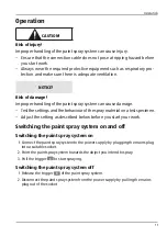
Page 17: ...ttings and the behaviour of the spray material on a test specimen Adjust the setting as described below before you start your work Switching the paint spray system on and off Switching the paint spray system on 1 Connect the paint spray system to the power supply by plugging the mains plug into a suitable socket 2 Point the paint spray system towards the object you intend to spray 3 Pull the trigg...

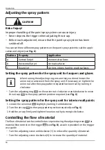
Page 18: ...e spray unit If necessary re tighten the union nut after the spray pattern required has been set by turning it clockwise Turn the adjusting ring 12 on the union nut clockwise or anticlockwise to move the air cap 19 to the spray pattern position required see Fig G Setting the spray pattern for the spray unit for interior wall paints 1 Loosen the union nut 4 slightly by turning it anticlockwise 2 Tu...

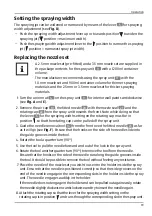
Page 19: ... setting on the rotating cap must be in position so that the rotating cap can be pulled off the spray unit 3 Guide the needle removal tool 14 from the front over the fitted needle 23 as far as it will go see Fig F Ensure that the hooks on the side of the needle slide into the guide grooves inside the tool 4 Rotate the tool a quarter turn 90 5 Use the tool to pull the needle forward and out of the ...

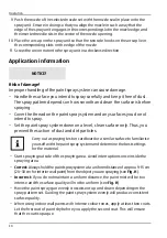
Page 20: ...o not intend to spray Set the paint spray system down on a level clean surface only Thus you prevent the suction of dust and dirt particles Carry out a spraying test on cardboard or a similar surface to familiarise yourself with the paint spray system and determine the best settings for the material Start spraying outside of the spraying area Avoid interruptions once inside the spraying area Corre...

Page 21: ...t Do not use flammable materials for cleaning Cleaning the spray unit NOTICE Risk of damage Dried spraying material can block the spray unit so that it cannot be used for the next spraying project Clean the spray unit after each use before the spray material dries Cleaning the paint container suction tube and ventilation tube 1 Before cleaning pull the mains plug out of the socket 2 If necessary r...

Page 22: ... paint container seal 27 free of material and check it for damage 18 Clean the outside and inside of the spray unit and the paint container with a cloth soaked in solvent or water 19 Let all parts dry thoroughly Cleaning the nozzle 1 Unscrew the union nut 4 or union nut 12 with adjusting ring from the spray unit 9 11 see Fig A and E 2 Remove the air cap 19 the nozzle 20 with the nozzle seal 21 and...

Page 23: ...place onto the spray unit Ensure in doing so that you align the nozzle in such a way that the edge of the spray unit engages in the corresponding slot in the nozzle edge and the inserted needle sits in the centre of the nozzle opening 14 Place the air cap on the spray unit so that the two side hooks on the air cap lie in the corresponding slots on the edge of the nozzle 15 Screw the union nut or u...

Page 24: ...s vacuumawaydustusingavacuumcleanerwiththefiltercoverinplace or remove the filter cover and take out the air filter as described below Then knock or blow the dust deposits off the air filter and replace the air filter as described below 1 Remove the four screws that attach the filter cover by turning them anticlockwise see Fig L 2 Remove the filter cover from the back of the motor unit 3 Remove th...

Page 25: ...rips out of the nozzle Nozzle loose Tighten the nozzle Nozzle worn out Change the nozzle Nozzle seal worn out Change the nozzle seal Build up of material in the air cap and nozzle Clean the air cap and nozzle Spray not fine enough Material viscosity too great Thin the material Adjusting screw for ma terial flow control turned too far to the right Turn the adjusting screw for material flow control ...

Page 26: ... to the object Spare parts and accessories You can order suitable spare parts and accessories for your paint spray system online www einhell co uk You will find current prices and information here You should provide the following data when ordering spare parts Model DS FSS 500 Article number Einhell 42 600 33 Identification no 11018 Spare part number of the spare part required can be found at www ...

Page 27: ...nal cautionary measures are necessary or not Factors that could affect the respective emission level present at the workplace include the specifications of the work area the surrounding area the duration of exposure other noise sources etc You must also observe any divergences in national regulations with respect to the permissible workplace levels The aforementioned information does however allow...

Page 28: ... Depending on the type of use or conditions of use the following safety measures must be taken to protect the user Avoid exposure to vibrations as much as possible Only use accessories in perfect working order Wear vibration proof gloves when using the paint spray system Maintain and service the paint spray system in accordance with this user manual Avoid using the paint spray system at temperatur...

Page 29: ...nic equipment WEEE This product must be handed in at a collection point intended for the purpose This can occur for example by handing it in at an authorised collecting point for the recycling of waste electrical and electronic equipment Owing to potentially hazardous substances that are frequently contained in waste electronic equipment incorrect handling of waste equipment may have a negative im...

Page 30: ...un standartiem LT apibūdina šį atitikimą EU reikalavimams ir prekės normoms RO declară următoarea conformitate conform directivei UE şi normelor pentru articolul GR δηλώνει την ακόλουθη συμμόρφωση σύμφωνα με την Οδηγία ΕΚ και τα πρότυπα για το προϊόν HR potvrđuje sljedeću usklađenost prema smjernicama EU i normama za artikl BIH potvrđuje sljedeću usklađenost prema smjernicama EU i normama za artik...

Page 31: ...re within its intended use over the course of the first 3 years after date of purchase we will remedy the problem as quickly as possible once it has been brought to our attention In the unlikely event of such an occurrence or if you require any information about the product please contact us via our helpline support services details of which are to be found both in this manual and on the product i...

Reviews: