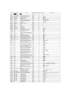
11130040
C/R
1/8W,1KΩ,±5%,brede style
PCS
6
1 R8,R9,R14,R29,R32,R38
11130051
C/R
1/8W,2.7KΩ,±5%,brede style
PCS
2
1 R15,R21
11130052
C/R
1/8W,3K,±5%,brede style
PCS
1
1 R50
11130059
C/R
1/8W,4.7KΩ,±5%,brede style
PCS
3
1 R10,R23,R53
11130060
C/R
1/8W,5.1KΩ,±5%,brede style
PCS
3
1 R2,R16,R20
11130061
C/R
1/8W,5.6KΩ,±5%,brede style
PCS
2
1 R3,R24
11130066
C/R
1/8W,9.1KΩ,±5%,brede style
PCS
1
1 R44
11130067
C/R
1/8W,10KΩ,±5%,brede style
PCS
5
1 R6,R40,R41,R11,R46
11130075
C/R
1/8W,18KΩ,±5%,brede style
PCS
1
1 R28
11130076
C/R
1/8W,20KΩ,±5%,brede style
PCS
1
1 R45
11130080
C/R
1/8W,30KΩ,±5%,brede style
PCS
1
1 R42
11130086
C/R
1/8W,51KΩ,±5%,brede style
PCS
1
1 R4
11130094
C/R
1/8W,100KΩ,±5%,brede style
PCS
3
1 R39,R49,R47
11130190
C/R
1/4W,68Ω,±5%,brede style
PCS
2
1 R22,R25
11130410
C/R
1/2W,220Ω,±5%,brede style
PCS
1
1 R35
11130210
C/R
1/4W,1KΩ,±5%,brede style
PCS
1
1 R19
11130220
C/R
1/4W,3KΩ,±5%,brede style
PCS
2
1 R30.R31
11110091
MO/R
1W,4.7Ω,±5%,vertical
PCS
1
1 R27
11110235
MO/R
3W,0.2 Ω,±5%,horizontal ,P=25mm.H=10mm.
PCS
2
1 R33,R34
50010001
C/C
5PF,VDC50,+/-5%,NPO,vertical and round
type,brede stylebrown
PCS
1
1 C22
50010016
C/C
22PF,VDC50,+/-5%,NPO,vertical and round
type,brede style,brown
PCS
2
1 C13,C14
50010029
C/C
47PF,VDC50,+/-5%,NPO,vertical and round
type,brede style,brown
PCS
1
1 C25
50010041
C/C
101,VDC50,+/-5%,NPO,vertical and round
type,brede style,brown
PCS
2
1 C33,C34
50010154
C/C
561,VDC50,+/-10%,Y5P(Y5E),vertical and round
type,brede style,brown
PCS
6
1 C7,C8,C16,C18,C26,C27
50010051
C/C
102,VDC50,+/-10%,Y5P,vertical and round type
,brede style,brown
PCS
1
1 C28
50010066
C/C
104,VDC50,+80/-20%,Y5V,vertical and round
type,brede style,brown
PCS
2
1 C3,C4
50020004
polyester capacitance
103,/-5%,vertical and adhesive type
,P=5mm,cutting the pin to be 6mm,green
PCS
1
1 C21
50020006
polyester capacitance
104,/-5%,vertical and adhesive
type,P=7.5mm,cutting the pin to be 6mm,green
PCS
2
1 C15,C17
17010305
E/C
0.47uF/50V,±20%,105℃,Φ5*11mm,P=2.0mm,blac
k,cutting the pin to be 6mm
PCS
1
1 C36
17010100
E/C
1uF/50V,±20%,-
40/+105℃,Φ5*11mm,P=2mm,black,cutting the pin
to be 6mm
PCS
1
1 C5
17010143
E/C
22uF/50V,±20%,-
40/+105℃,Φ5*11mm,P=2mm,black,cutting the pin
to be 6mm
PCS
4
1 C10,C11,C23,C29,
17010204
E/C
100uF/25V,±20%,-
40/+105℃,Φ6.3*11mm,P=2.5mm,black,cutting the
pin to be 6mm
PCS
1
1 C35
17010307
E/C
220uF/16V,±20%,105℃,Φ6.3*11mm,P=2.5mm,bla
ck,cutting the pin to be 6mm
PCS
1
1 C12
17010308
E/C
220uF/25V,±20%,105℃,Φ6.3*14mm,P=2.5mm,bla
ck,cutting the pin to be 6mm
PCS
3
1 C24,C19,C20
50080006
X2 approvaled cap
104/275V,+/-10%,vertical and box
type,P=10mm,cutting the pin to be 6mm,yellow
PCS
2
1 CX1,CX2
18010017
diode
D-41,1N4004,brede style
PCS
2
1 D5,D6
18010039
diode
DO-201AD,1N5401,brede style
PCS
4
1 D1~D4
18010009
diode
DO-35,1N4148,brede style
PCS
1
1 D7
18010007
diode
DO-35,1N4148,horizontal,P=7.5MM
PCS
2
1 D8,D9
18030026
zener diode
DO-35,1/2W,15V,brede style
PCS
3
1 ZD1,ZD4,ZD5
14020024
PNP TR
2SA1015GR,TO92 side-pins moulding and brede
style,TOSHIBA
PCS
3
1 Q21,Q22,Q1
14010026
NPN TR
2SC1815GR,TO92side-pins moulding and brede
style,TOSHIBA
PCS
3
1 Q9,Q12,Q2
14010036
NPN TR
2SC2878-B,TO92side-pins moulding and brede
style TOSHIBA
PCS
1
1 Q15
14020022
PNP TR
2SA970BL,TO92 side-pins moulding and brede
style,TOSHIBA
PCS
1
1 Q19
14010033
NPN TR
2SC2240BL,TO92 side-pins moulding and brede
style,TOSHIBA
PCS
2
1 Q14,Q23
14020021
PNP TR
2SA965,TO92 side-pins moulding and brede style PCS
1
1 Q20
14010032
NPN TR
2SC2235,TO92 side-pins moulding and brede style
TOSHIBA
PCS
1
1 Q16
40370016
JACK
AN-JP402,2532-02, (180degree,P=2.5mm)
PCS
1
1 CN1-A
40370034
JACK
AN-JP403,2532-05, (180degree,P=2.5mm)
PCS
1
1 CN2-B
26010022
PCB
GAX-POWER&,94V0 single panel,AN-
B10023,green,V1.2,1ounce
PCS
1
1 GAX-POWER& V1.2
40370005
JACK
AN-JP401,2532-06, (180degree,P=2.5mm)
PCS
1
1 CN5-B
17010292
E/C
1000uF/25V,±20%,-
40/+105℃,Φ10*16mm,P=5mm,black,cutting the pin
to be 6mm
PCS
1
1 C6
17010085
E/C
4700uF/50V,±20%,-
40/+105℃,Φ22*40mm,P=10mm,black
PCS
2
1 C1,C2
14010005
NPN TR
HMPSA13,TO92 side-pins moulding and brede
style
PCS
1
1 Q13
14010084
NPN TR
TIP41C,TO-220,ST(10A,100V,65W)
PCS
1
1 Q17
14020047
PNP TR
TIP42C,TO220,ST
PCS
1
1 Q18
14040030
IC
L7805CV,TO220,ST
PCS
1
1 U1
40030009
6.35FAUCET
AN-J0309,SCJ630R0NCS1BK0
PCS
1
1 J9
40030008
6.35FAUCET
AN-J0308,SCJ630R0NAS1BK0
PCS
2
1 J6,J7
40030010
6.35FAUCET
AN-J0310,SCJ630R0NDS1BK0
PCS
1
1 J3
40030024
6.35FAUCET
AN-J0328,SCJ638R4NDS5BP0
PCS
1
1 J10
40190016
RCA JACK
AN-J1916,RCA-204A, (2P,left is red and right is
white ,plating nickel )
PCS
1
1 RCA
10490004
inserting sheet
E665 ,P=5.0mm
PCS
6
1 WT-A,BK-A,RD-A,T230,T120,T00
12100001
temperature swtich
AN-SA01,UP72-85degree,the length of wire is
110mm
PCS
1
1
Summary of Contents for BASSFIRE 60
Page 5: ......
Page 6: ...Confidential Alesis Service Manual 8 31 0159 A ALESIS BassFire 60 GB0 Test Procedures...
Page 17: ...Confidential Alesis Service Manual 8 31 0159 A ALESIS BassFire 60 GB0 SCHEMATIC AND PCB FILES...
Page 18: ...GAX_MAIN_V1 1 sch 1 Mon Feb 28 16 17 24 2005...
Page 19: ...GAX_MAIN_V1 1 sch 2 Mon Feb 28 16 17 26 2005...
Page 20: ......
Page 21: ......
Page 22: ...sch 1 Mon Feb 28 16 08 43 2005...
Page 23: ...sch 1 Mon Feb 28 16 07 56 2005...
Page 24: ......
Page 25: ......
Page 26: ......
Page 27: ......
Page 28: ......
Page 29: ......
Page 30: ......
Page 31: ......
Page 32: ......
Page 33: ......
Page 34: ......
Page 35: ......
Page 36: ......
Page 37: ......
Page 38: ......
Page 39: ...Confidential Alesis Service Manual 8 31 0159 A ALESIS BassFire 60 GB0 BOM...

