HR-16/HR16B Service Manual 1.00
4
3.2 Memory Mapped I/O
In order to easily control the vast number of hardware functions that the 8031 needs to
access, a system of memory mapped I/O is used. The basic idea is to make hardware functions
appear to the 8031 as unused memory locations. That way all that the software has to do is write to
a memory location in order to send that information to a specific device such as the LCD, or ASIC.
74HC138 (U13) performs the majority of the work in this circuit. Two things are required
before U13 becomes active. 1> A15 must be low (i.e. the 8031 is accessing the lower 32K of
address space). 2> The 8031 WRite line must be active (the 8031 is performing a memory write).
A15 is used to directly control which function (memory or I/O) is active.
Once U13 is enabled, addresses A8-A10 are decoded by it, and the latch corresponding to
the value of the decoded address is strobed. At this point, data on the 8031 data buss is "written"
into the latch.
3.3 Keypad I/O
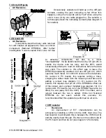
Keypad I/O is handled through a simple polling process Each row of the keypad matrix is
pulled low one at a time (via U14 which is memory mapped). If any button along the row is pressed,
the corresponding
column input (U22) will
appear high. If no
buttons are pressed, all
column inputs will
appear as a low. D9-
D15 and R42-R47
provide protection for
the outputs of U14. Use
diagram 3 to localize
individual button
failures.
3.4 MIDI I/O
The MIDI
hardware is a standard
implementation. MIDI
out begins at the
8031's TXD port (pin
11) and travels via R6
to the darlington pair
Q1/Q2. Note that the
8031's internal pullup is
not very strong, and
older units (revision A)
may require the addition of an external pullup resistor for the MIDI out to function correctly (see
section 7.7).
MIDI in consists mostly of the opto isolator (U4), protection diode D6, pullup R7, and
threshold resistor R5. Note that the threshold resistor may need to be changed in order to eliminate
false MIDI triggers (see section 7.6).
Diagram 3


