background image

9

Maintenance

9.6

Replacing the impeller and mechanical seal for

pump

G09869a1

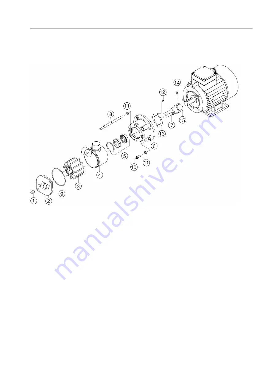
1. Screw cap
2. Cover
3. Impeller
4. Pump body
5. Mechanical seal

(Carbon/Ceramic/Nitrile)

6. Motor flange
7. Shaft
8. Screw stud
9. O-ring
10. Screw

11. Washer
12. Screw
13. Washer
14. Lock screw
15. Sleeve

Dismantling of impeller and mechanical seal

1.

Check that hoses between the cleaning unit
and the tank to clean are removed.

2.

Disconnect the hoses from the pump in-
and outlet.

3.

Place a vessel under the pump to collect
leaking liquid at dismantling.

4.

Remove the front cover (2) and the O-ring
(9).

55

Summary of Contents for Alfie

Page 1: ...Book No 9017117 02 Rev 8 Alfa Laval Alfie Cleaning system for liquids Product No 9016086 80 81 9016092 80 81 Instruction Manual ...

Page 2: ...n Telephone 46 8 530 650 00 Telefax 46 8 530 310 40 Alfa Laval Tumba AB 05 2016 Original instruction This publication or any part there of may not be reproduced or transmitted by any process or means without prior written permission of Alfa Laval Tumba AB ...

Page 3: ...rking principle of the separator 19 6 Control Cabinet 21 6 1 Operator panel 21 6 2 Connection for correct voltage 27 6 3 Alarm light pattern 28 6 4 Alarm table 29 7 Operating instructions 31 7 1 Before first start 31 7 2 Before normal start 31 7 3 Start 31 7 4 Operation 35 7 5 Standby 35 7 6 Stop 35 8 Trouble shooting 37 8 1 Cleaning system separator does not start or stops shortly after start 37 ...

Page 4: ...ting tank when separator is not running 41 8 13 Collecting tank overflowing but pump does not stop 41 8 14 Insuficient separation result 42 9 Maintenance 43 9 1 Cleaning 43 9 1 1 Strainer 43 9 1 2 Separator 43 9 2 Once per month 44 9 2 1 Pump 44 9 3 Once per year 44 9 3 1 Separator 44 9 4 Every second year 45 9 4 1 Separator 45 9 5 Dismantling assembly instructions for separator 45 9 5 1 Introduct...

Page 5: ...10 2 Declaration 58 11 Lifting instruction 59 11 1 Cleaning unit 59 12 Diagrams 61 12 1 Electrical system 61 5 ...

Page 6: ......

Page 7: ...d or injury The following basic safety instructions therefore apply Use the cleaning unit only for the purpose and parameter range specified by Alfa Laval Only use the cleaning unit in non explosion environment Strictly follow the instructions for installation operation and maintenance Ensure that personnel are competent and have sufficient knowledge of maintenance and operation Use only Alfa Lava...

Page 8: ...efore moving the cleaning unit or starting any dismantling work To avoid accidental start switch off the power supply and remove the electric cable from the socket before starting any dismantling work Warning label located on separator hood Warning labels A warning label is placed on the separator hood The interpretation of the label is STOP Read the instruction manual before installation operatio...

Page 9: ...Alfie 500 cleaning system is restricted to the removal of solids and oil from liquids with a temperature range between 15 and 70 C WARNING Disintegration hazard The cleaning system must not be operated in an explosion environment 9 ...

Page 10: ...2 Application ...

Page 11: ...911 NOTE When ordering spare parts for the cleaning unit except the separator please specify the article and serial numbers stamped on the machine plate 1 for the complete unit NOTE When ordering spare parts for the separator itself please specify the type product and serial numbers stamped on the machine plate 2 for the separator 11 ...

Page 12: ...r separation G Manufacturer H Serial No I Enclosure Article No Serial No Year Manufacturer Alfa Laval Krakow Service enquiries www alfalaval com A B C G1102721 Example of machine plate complete unit A Article No B Serial No C Manufacturing Year Note that the illustrations are examples of a machine plates Values shown on the illustrations are not valid for all machines 12 ...

Page 13: ...ore the feed enters the separator 4 Pump Feed pump for the liquid The pump speed is raised until the counter pressure in the outlet line passes 50 kPa 5 Separator Removes oil and solids from the liquid The separator has a bowl hood interlock over the hood and connection housing A magnetic switch indicates if the interlock is in correct position If not the control system prohibits the unit from sta...

Page 14: ...ing tension and a limit switch is actuated The signal goes to the control unit 9 which stops the pump 4 An alarm alerts the operator 9 Control cabinet further described in chapter 6 Control Cabinet on page 21 The control system supervises the starting and stopping of the cleaning unit It also supervises system functions such as frequency converters one for the separator and one for the pump motor ...

Page 15: ...4 Description of main parts 1 2 8 7 6 5 4 3 9 10 G1102011 A suction device of bellows type can preferably be used in shallow tanks 55 100 mm 15 ...

Page 16: ...e motor For a description of the separator function see 5 Working principle of the separator on page 19 G0907931 4 3 Pump The flow is controlled by the VFD in the control cabinet see chapter 6 Control Cabinet 4 4 Control unit The Control unit consist of following main parts 1 Power supply 24 V DC 2 PLC kit 3 Frequency converter separator 4 Frequency converter feed pump 5 Mini terminal 6 Contactor ...

Page 17: ...by a spring with adjustable tension The spring can be adjusted by the handle 1 on the underside of the support When the collecting tank is nearly full the weight will overcome the spring tension and a limit switch is actuated The signal goes to the control unit which stops the pump The lamp on the control unit lights up 1 G1113211 17 ...

Page 18: ...4 Description of main parts ...

Page 19: ...ing the separation process The oil light phase is forced towards the centre of the bowl and then leaves through the underside of the bowl at C down into the collecting tank The speed of the electric motor 6 driving the bowl spindle 5 is regulated by a frequency converter which by that eliminates any use of a transmission such as a gear or a belt The converter also acts as a brake when the separato...

Page 20: ...5 Working principle of the separator ...

Page 21: ...f the separator and the pump a 24VDC power supply and a PLC There are no operator controls inside the cabinet so it should not be opened Qualified personnel only are allowed to open the cabinet On top of the cabinet there is also an alarm light It is used to indicate the status of the unit See 6 3 Alarm light pattern on page 28 6 1 Operator panel 1 2 3 4 5 6 G1113881 1 Start button 2 Stop button 3...

Page 22: ...e the corresponding button is circled in green The Alarm button takes the operator directly to the Alarm list see Alarm list on page 30 If there is an active alarm the button will be red The Back Overview button has different functions depending of which screen is displayed If Back is displayed the button will switch to the previous screen If Overview is displayed it will switch to the overview sc...

Page 23: ... sub equipment On the left hand side there is a status row for the sub equipment and if applicable setpoints for the devices and control functions for that subequipment On the right hand side is a graphical overview of the sub equipment Each device is circled green if running or open and red if an alarm exists for that device Actual values such as pressure readings and speed are displayed next to ...

Page 24: ...ure control screen shows the pressure sensor and the pressure regulation valve Pressure set point can be changed from here By tapping the set point value a touch dial will appear G1113841 When the unit is at standstill the operator can switch to Service mode and enable manual control of the regulating valve This is only intended as an operational test of the valve It cannot be used when the unit i...

Page 25: ...nistrator NOTE Administrator access level is only for Alfa Laval service engineers Alarm history A list of all past alarms System time Set system time so correct time stamps are made in the alarm list Language Set system language Login Login and logout to change access level Operating timers Separate running timers are available for System Separator motor Feed pump motor and Regulating valve Syste...

Page 26: ...can be for operator information only but in most cases it also forces the unit to another operating mode See 6 4 Alarm table on page 33 The operator acknowledges alarms with the two buttons on the right hand side Red indicates an unacknowledged alarm yellow an acknowledged but still active alarm and green an unacknowledged but no longer active alarm 26 ...

Page 27: ...should be equipped with a transformer 1 Other possible voltages are then 100 110 and 120 V Switching between voltages requires changing of transformer connection inside the control cabinet See circuit diagram This should only be done by qualified personnel If a transformer is connected first check that the power cable is correctly connected in the control unit before operating the cleaning unit Fo...

Page 28: ...y shine During START If an active alarm that has been acknowledged exists During STOP as long as separator is not in standstill Blinking 0 5s on 0 5s off When feed pump speed is boosted Startup speed If an unacknowledged alarm exists Flashing 0 2s on 2s off If system is in STANDBY and no alarm is active 28 ...

Page 29: ... temp cabinet 15s High temperature in control cabinet Check ventilation for control cabinet A100 Feed pump motor overload 1s Frequency converter fault for feed pump Check motor connection Check pump motor Check control cables to Frequency converter A200 Bowl hood interlock open 1s Bowl hood interlock out of correct position See 8 1 Cleaning system separator does not start or stops shortly after st...

Page 30: ...6 Control Cabinet ...

Page 31: ... as illustrated Fill the inside of the bellows with liquid by pressing it below the surface The device 1A is floating while 1B stands on the tank bottom 4 Check that the hose for the feed inlet 2 is connected to the strainer Admitted suction height for the separator is max 1 7 metres 5 Check that the return hose for the feed outlet 3 is placed securely in the tank and far away from the feed inlet ...

Page 32: ...ructions 6 5 4 1A 3 2 1B 7 G1102311 1a Suction device for deeper tanks min 100 mm 1b Suction device for shallow tanks 55 100 mm 2 Feed inlet 3 Feed outlet 4 Hood screws 3 pcs 5 Knob 6 Bowl hood interlock 7 Strainer 32 ...

Page 33: ...ow running in Production mode G1106011 Disintegration hazard Some vibration can occur for short periods during the start phase when the separator passes through the critical speed This is normal and passes over without danger If the vibration becomes very severe or continues at full speed stop the separator immediately See chapter 8 6 Separator vibrates on page 39 for possible causes 3 Check that ...

Page 34: ...1 4 Increase the counter pressure slowly until a small stream of oil liquid is observed coming from the oil outlet 1 Preferably use a torchlight to see this Reduce the counter pressure to increase the oil concentration or increase the counter pressure to improve the oil removal efficiency of the separator 5 After adjustment of the counter pressure check that the pressure is within the recommended ...

Page 35: ... regulating valve is opened The operator can also choose to go to Standby by tapping the Standby button When there are no alarms active and unacknowledged the operator can tap the Start button to resume separation by returning to Production mode NOTE If an alarm has forced the system into standby never do more than one pump restart Check and remedy the cause Several restarts can damage the pump wh...

Page 36: ...g tank NOTE If the position of the tank level is higher than the inlet outlet of the separator there is a risk that liquid may be siphoned from the tank and drained via the separator into the collecting tank NOTE If the cleaning unit is not used for a longer period drain the pump from liquid The rubber material of the impeller ages and should be treated as perishables 36 ...

Page 37: ...ansformer Separator stops See 8 4 Separator stops on page 38 Pump stops See 8 3 Pump stops on page 37 8 2 Pump does not start Possible cause Action Microswitch for filled collecting tank activated Empty the tank or adjust the spring tension for the tank support 8 3 Pump stops Possible cause Action Collecting tank filled Empty the tank and start the pump Overload caused by clogged strainer Clean th...

Page 38: ...stack Overload due to incorrect assembly Check the bowl assembly Tripped frequency converter due to too low or too high supplied voltage 5 of nominal voltage Check the voltage Check the voltage If unstable voltage connect a transformer Also see possible causes and actions in 8 1 Cleaning system separator does not start or stops shortly after start on page 37 Defective frequency converter Replace f...

Page 39: ...tor bowl Be sure that the separator is assembled correctly Vibration dampers in separator are worn Fit new dampers Damaged bearings Replace the bearings 8 7 No flow from pump Possible cause Action Incorrect setting of flow control too low speed of pump Start with max flow See 6 Control Cabinet The screw fitted in pump is not closed internal leakage too high Turn the adjustment screw clockwise Air ...

Page 40: ... correctly Separator or pump rotates in wrong direction Check power supply cables 8 9 No flow either through clean oil outlet or through drain to collecting tank Possible cause Action Separator or pump stopped Check function see 8 4 on page 38 and 8 3 on page 37 Inlet and outlet hoses for pump wrongly connected Interchange the hose connections Strainer before separator clogged Clean strainer Separ...

Page 41: ...o collecting tank only Possible cause Action If operating in purifier mode broken liquid seal in separator bowl Stop the pump and add water through the inlet at top of the separator Obstruction in cleaned oil feed line Check that regulating valve is open Check that outlet end to tank is open no closed check valve in hose connection 8 12 Oil leakage through drain outlet to collecting tank when sepa...

Page 42: ...tank lays too high Adjust the height See description in chapter 7 3 Start on page 31 Separator disc stack clogged Clean separator bowl and disc stack The counter pressure is too low Increase the counter pressure until oil is observed to be discharged from the oil outlet see chapter 7 3 Start on page 31 42 ...

Page 43: ...sary cleaning interval NOTE When fitting the filter housing it must first be filled with liquid to prevent the pump operating in dry condition Otherwise the life of pump will be shortened 9 1 2 Separator The separated solids collected inside the separator bowl must be removed manually The length of the cleaning interval depends on the liquid flow rate and on the amount of solids During the initial...

Page 44: ...ler are not broken If a vane is brooken replace with a new impeller Always check that rubber parts from the impeller does not block the hoses or separator inlet including the inlet pipe If blocked the new impeller will break very quickly The impeller is a wearing part and the performance of the pump will change with the wear Abrasive liquids will shorten the service life of the impeller and the pu...

Page 45: ...very second year 9 4 1 Separator Check replace the disc stack to maintain the separation efficiency See 9 5 3 Replacement of O rings on page 50 for procedure 9 5 Dismantling assembly instructions for separator 9 5 1 Introduction The illustrations on the following pages describe step by step how to dismantle clean replace and assemble the various parts of the separator The illustrations have symbol...

Page 46: ...d too soon the following could happen The pin on the inside of the connecting housing breaks The pin inside the top of the paring disc breaks Excessive wear of top of level ring Illustration 8 Some coolant will normally leak from the connecting housing when the frame hood is opened If coolant continues to leak the cause could be a non sealing check valve if any while the separator is connected to ...

Page 47: ...9 Maintenance Dismantling G04491c1 See comments on opposite page 47 ...

Page 48: ...t fit the level ring and then the O ring outside the level ring Finally press down the O ring by pressing the cover 3 firmly with both hands G0912121 G0907211 Illustration 18 Check that the distance illustrated is max 0 5 mm If not the reason could be 1 The O ring outside the level ring is not in the downwards position or the O ring is located under the level ring 2 Two washers are fitted under th...

Page 49: ...ed on the connecting housing before tightening the screws shown in illustration 23 Otherwise there is a risk that the pin inside the connecting housing could break Assembly 16 0 5 mm 21 24 25 20 17 18 19 26 23 3x 22 G0449281 See comments above and on opposite page 49 ...

Page 50: ...3 Check that the washer is fitted Otherwise there is a risk that the bowl will not make firm contact with the spindle If two or more washers are fitted accidentally this will prevent the top parts of the bowl from being positioned correctly Illustration 15 NOTE Fit the upper O ring outside the level ring see comments to illustration 17 50 ...

Page 51: ...9 Maintenance First dismantle the separator bowl as described in 9 5 2 Cleaning of bowl on page 46 3 4 5 7 15 11 12 14 10 1 2 13 6 8 9 G05191j1 See comments on opposite page 51 ...

Page 52: ...9 Maintenance 9 5 4 Replacement of motor bearings First dismantle the separator bowl as described in 9 5 2 Cleaning of bowl on page 46 G0449461 52 ...

Page 53: ...9 Maintenance G0449671 53 ...

Page 54: ...9 Maintenance G0449681 54 ...

Page 55: ...haft 8 Screw stud 9 O ring 10 Screw 11 Washer 12 Screw 13 Washer 14 Lock screw 15 Sleeve Dismantling of impeller and mechanical seal 1 Check that hoses between the cleaning unit and the tank to clean are removed 2 Disconnect the hoses from the pump in and outlet 3 Place a vessel under the pump to collect leaking liquid at dismantling 4 Remove the front cover 2 and the O ring 9 55 ...

Page 56: ... Slide the rotating seal part onto the shaft with a twisting movement and press the stationary seal part into the pump body Lubrication with soap solution will ease the assembly 2 Assemble the pump body to the flange taking care not to damage the seal G09869c1 3 Lubricate the impeller with grease or vaseline 4 Push the impeller into the pump body with a twisting movement in the operating direction...

Page 57: ... litres hour 50 60 Hz Max ambient temperature 45 C Counter pressure at outlet of unit Recommended 100 180 kPa Max 185 kPa Suction height Max 1 7 metres Volume in collecting tank 20 litres Power supply 230 V 5 1 phase 50 60 Hz 100 110 120 V 5 1 phase 50 60 Hz option with fitted transformer Amperage 10 A 230 V 16 A 100 120 V Sound Sound power Max 8 9 Bel A ISO 3744 Sound pressure level Max 75 dB A I...

Page 58: ...ral requirements EN 61000 6 2 Electromagnetic compatibility EMC Part 6 2 Generic standards Immunity for industrial environments EN 61000 6 4 Electromagnetic compatibility EMC Part 6 4 Generic standards Emission standard for industrial environments EN ISO 12100 Safety of machinery General principles for design Risk assessment and risk reduction EN ISO 13849 1 Safety of machinery Safety related part...

Page 59: ...nd crane hook should be min 1 metre A NOTE Weight of unit is approx 60 kg WARNING Entrapment hazard Only attach the lifting straps to the two lifting hooks when lifting the cleaning unit A falling unit can cause accidents resulting in serious injury to persons and damage to equipment G1102411 Lifting procedure for cleaning unit 59 ...

Page 60: ...11 Lifting instruction ...

Page 61: ...12 Diagrams 12 1 Electrical system Alfa Laval ref 9014733 Rev 7 61 ...

Page 62: ... 2015 10 23 Approved by SETUNLN CAT Department 2014 04 01 Created date Document No 9014733 Page Revision Latest Revision 07 Project Title page cover sheet Location Mounting Title Alfie Emmie Revised date 1 2 Next page Page 2014 09 05 Alfa Laval Tumba AB Project description Alfie Emmie Control voltage 2014 04 01 Edit date 230V AC 100 110 120VAC with optional transformer Created on Main supply 90147...

Page 63: ...ts Shield SH shall be connected to cable glands except for power supply cables they shall be connected to PE bar Page 25 244 IF2 1 CP01 A1 1 CP01 OP1 Ethernet to OP 1 GN YE GN YE Page 27 261 Tank full W201 PE W V SH SH Page 23 221 SH U CP01 U2 SH Field SH Shield connected in EMC cable gland Pump W003 1 1 Page 21 201 2 2 Page 21 201 GNYE GNYE Page 21 201 PE 2 1 CP01 X1 PE N L PS MAINS Power Supply ...

Page 64: ...W202 W401 W402 Location Mounting Title Alfie Emmie Revised date 07 3 4 Next page Page 2015 10 07 Internal targets External targets Shield SH shall be connected to cable glands except for power supply cables they shall be connected to PE bar BN BN Page 27 264 SH SH Page 29 282 CP01 SH Field SH Pressure regulating valve W402 2WH 2WH Page 21 208 CP01 X400 SH SH Page 26 255 CP01 SH Field SH Pressure t...

Page 65: ...y connected to earth as shown in the electrical drawings For power cables armour must be connected to the earth bar Providing the armour is connected to the earth as shown in the electrical drawings gives sufficient EMC protection Note 1 Cable not included in Alfa Laval delivery 2 Cable type and size according to VFD motor specification 3 Optional 4 If external transformer main supply is connected...

Page 66: ...tment 2014 04 01 Created date Document No 9014733 Page Revision Latest Revision 07 Project Wiring table Location Mounting 9014733 CP01 Title Alfie Emmie Revised date 02 10 11 Next page Page 2014 09 05 Wiring Table Wire Type N07V K or equivalent flame retardent Black Black Black Black Black Black Red Blue Yellow Green Orange Wire Colour Power Circuits Auxiliary Circuits 24VAC Auxiliary Circuits 24V...

Page 67: ...cabinet assembly Location Mounting 9014733 CP01 Title Alfie Emmie Revised date 07 11 12 Next page Page 2015 10 23 Technical data Hatch Back G1 O P T I O N A L 1 PE U2 11 12 10 10 2 9 5 3 7 6 4 IP54 SSAISI304 Stainless steel 1 5mm thickness EMC doorsealing Cable tray ABB T20 part No E2998812 or equivalent 30 Instructions Rectifier G1 must be mounted like shown to maintain maximum derating Use silic...

Page 68: ... 2015 10 23 Approved by SETUNLN CAT Department 2014 04 01 Created date Document No 9014733 Page Revision Latest Revision 07 Project Control cabinet assembly Location Mounting 9014733 CP01 Title Alfie Emmie Revised date 07 12 13 Next page Page 2015 10 23 295 370 410 180 59 Mounting bracket for hanging cabinet on toolbox 280 40 40 6 All meassurements in mm 151 83 Hatch Back O P T I O N A L 88 105 88...

Page 69: ...document constitutes a contractual obligation on our part only to the extent expressly agreed upon SETUTBL Created by SETUTBL Revised by Approved date 2015 10 23 Approved by SETUNLN CAT Department 2014 04 01 Created date Document No 9014733 Page Revision Latest Revision 07 Project Control cabinet assembly Location Mounting 9014733 CP01 Title Alfie Emmie Revised date 02 13 14 Next page Page 2014 09...

Page 70: ...on This document constitutes a contractual obligation on our part only to the extent expressly agreed upon SETUTBL Created by SETUTBL Revised by Approved date 2015 10 23 Approved by SETUNLN CAT Department 2014 04 01 Created date Document No 9014733 Page Revision Latest Revision 07 Project Terminal assembly Location Mounting 9014733 CP01 Title Alfie Emmie Revised date 06 14 15 Next page Page 2015 0...

Page 71: ...tutes a contractual obligation on our part only to the extent expressly agreed upon SETUTBL Created by SETUTBL Revised by Approved date 2015 10 23 Approved by SETUNLN CAT Department 2014 04 01 Created date Document No 9014733 Page Revision Latest Revision 07 Project PLC Assembly Location Mounting 9014733 CP01 Title Alfie Emmie Revised date 05 15 21 Next page Page 2015 01 14 A1 A1 X1 A2 A1 X2 A1 X3...

Page 72: ... Page 2015 10 23 Power Supply 1x230V 50 60Hz Max fuse 10A Option 1x100 110 120V 50 60Hz Max fuse 10A 24V DC PLUS G1 AC 100 120 200 240V DC 24V 2 5A 120W 144W L N PE 24V DC MINUS EMC 2 stage filter Remove when using optional transformer Isolated if not used Optional transformer with 100 110 120VAC supply 100VAC Input 230VAC Output 110VAC Input 120VAC Input 120 BU MAINS L N CUSTOMER PS PE 2 5 2 5 PE...

Page 73: ...d date Document No 9014733 Page Revision Latest Revision 07 Project Separator Location Mounting 9014733 CP01 Title Alfie Emmie Revised date 05 22 23 Next page Page 2015 01 13 S1 I ON Separator Note Settings according to parameter list GND X1A 3 AI X1A 2 SRC X1A 1 RONO X1B 3 RONC X1B 2 ROCOM X1B 1 BRK BRK W1 PE PE W2 V2 U2 U1 V1 DI3 X1A 10 DI2 X1A 9 DI1 X1A 8 DCOM X1A 7 GND X1A 6 24V X1A 5 U1 ACS15...

Page 74: ...roved date 2015 10 23 Approved by SETUNLN CAT Department 2014 04 01 Created date Document No 9014733 Page Revision Latest Revision 07 Project Pump Location Mounting 9014733 CP01 Title Alfie Emmie Revised date 04 23 24 Next page Page 2014 12 01 Pump Note Settings according to parameter list AI I U SPEED AI 3 COM 1 RO2 RO RO1 RO PE PE W V U L R N S START 6 COM 2 U2 ACS55 01E 04A3 2 PE U1 V1 W1 PE M2...

Page 75: ...ligation on our part only to the extent expressly agreed upon SETUTBL Created by SETUTBL Revised by Approved date 2015 10 23 Approved by SETUNLN CAT Department 2014 04 01 Created date Document No 9014733 Page Revision Latest Revision 07 Project HMI Panels Location Mounting 9014733 CP01 Title Alfie Emmie Revised date 06 24 25 Next page Page 2015 03 24 HMI Cabinet 1 Ethernet OP1 24V 0V PE Ethernet t...

Page 76: ...ocument constitutes a contractual obligation on our part only to the extent expressly agreed upon SETUTBL Created by SETUTBL Revised by Approved date 2015 10 23 Approved by SETUNLN CAT Department 2014 04 01 Created date Document No 9014733 Page Revision Latest Revision 07 Project A1 CPU Location Mounting 9014733 CP01 Title Alfie Emmie Revised date 02 25 26 Next page Page 2014 09 05 USB IF4 Etherne...

Page 77: ...pproved by SETUNLN CAT Department 2014 04 01 Created date Document No 9014733 Page Revision Latest Revision 07 Project X1 Inputs Location Mounting 9014733 CP01 Title Alfie Emmie Revised date 06 26 27 Next page Page 2015 03 26 Pressure transmitter 11 AI 1I AnalogInput1 12 AI 1U Sens 13 AI 1U I Sens 14 DI1 DigitalInput1 15 DI3 DigitalInput3 21 AI 2I AnalogInput2 22 AI 2U Sens 23 AI 2U I Sens 24 DI2 ...

Page 78: ... Project X2 Inputs Location Mounting 9014733 CP01 Title Alfie Emmie Revised date 06 27 28 Next page Page 2015 03 26 Tank full Cover open Separator Fault Pump Fault 11 DI1 DigitalInput1 12 DI3 DigitalInput3 13 DI5 DigitalInput5 14 DI7 DigitalInput7 15 DI9 DigitalInput9 16 DI11 Fast DigitalInput11 17 DI13 Fast DigitalInput13 18 GND 21 DI2 DigitalInput2 22 DI4 DigitalInput4 23 DI6 DigitalInput6 24 DI...

Page 79: ...3 Outputs Location Mounting 9014733 CP01 Title Alfie Emmie Revised date 06 28 29 Next page Page 2015 03 24 Separator start Indication Common Alarm Pump start External Alarm ON NO ALARM Note 24VDC Max 0 5A Enable VFD separator 12 DO3 DigitalOutput3 11 DO1 DigitalOutput01 13 DI5 DO5 DI5 DO5 A1 X3 X20CP1301 14 DI7 DO7 DI7 DO7 15 DO9 DigitalOutput9 16 DO11 DigitalOutput11 17 24V CPU X2XL VDC 18 GND GN...

Page 80: ...06 Next page Page 29 Revised date 9014733 Document No 2015 03 26 Pump VFD speed Chanel 1 Chanel 2 Chanel 3 Chanel 4 X1 11 AO 01I AnalogOutput01 X1 14 AO 03I AnalogOutput03 X1 12 AO 01U AnalogOutput01 Field V1 1 4 X1 13 AO 01 AnalogOutput01 Field V1 1 3 X1 16 AO 03 AnalogOutput03 X1 15 AO 03U AnalogOutput03 A2 X20AO4622 X20 analog output module 4 inputs 10 V or 0 to 20 mA 4 to 20 mA 12 bit resoluti...

Reviews: