6. Maintenance
21
Read the instructions carefully. The items refer to the parts list and service kits section.
6.5
Reassembly
General Notes
All parts must be cleaned thoroughly before reassembling. Any deposits remaining on the parts can cause difficult disassembly
the next time the Alfa Laval Gamajet needs servicing.
Unless otherwise stated, apply a dab of a Teflon-based anti-seize compound to all threads when reassembling; this will prevent
galling of threads and ease any future disassembly.
To ease installation of all O-rings, they should be lubricated prior to reassembly. A Silicon based lubricant must be used for EP
O-rings (standard material, black colored (50)). Lithium-based grease is acceptable, for Viton
O-rings (caramel colored (50)).
In either case, however, a food grade lubricant may be used.
Refer to illustrations chapter 8 for clarification during reassembly.
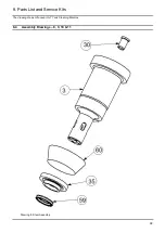
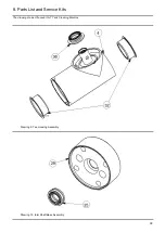
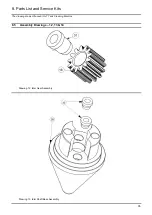
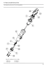
Drawing 8, 9, 10 & 11
Tee Housing
Turn to (drawing 8): Place the lower Tee Housing Bearing (35) & Seal (59) (spring side up) onto the Stem (3).
Push the Tee Housing (4) over it until it is flush and fully seated.
Place the combo Bearing and Seal (61) over Stem (spring side down) and push it down between (3) and the Tee Housing
Bearing Cup (32). (A large diameter pin will aid in the insertion). Use the Tee Housing Bevel Gear (17) to full seat the (61).
Turn to (drawing 11): Align the through holes of the (17) with the threaded holes in the top of the (3). Apply a small amount of a
mild thread lock to the four Phillips Pan Head Screws (44) and screw them in, tightening them in a star pattern. (Needle nose
pliers will help insert the small screws.) The (4) should not have any axial play.
Turn to (drawing 10): Ensure that the Output Shaft Lower Seal (25) is in the Idler Shaft Base (29) (spring side out). Then, repeat
the procedure in the previous step for the Idler Shaft Base (29). No thread lock is required for this set of four screws.
Insert the Ring Gear (20) into the Tee Housing, being sure to align the key and key way of the two components.
Reinstall the Ring Gear Retaining Ring (21).
Drawing 9, 15, 16
Nozzle Housing
Turn to (drawing 9): Place the first Nozzle Housing Bearing & Seal (36) (spring side out) onto the nose of the Tee Housing (4).
Turn to (drawing 15): If the unit is a
“Low-Pressure (Non-Teed) Version,” apply a small amount of mild thread lock to the
threads of each Nozzle (7) and screw them into the Nozzle Housing (5) with the aid of pliers.
Using your thumb, push the Nozzle Housing (5) onto the nose of the Tee Housing. Rotate the Tee Housing Assembly slightly to
mesh the Bevel Gears (17) and (18). Failure to ensure that the Bevel Gears have properly mated could damage them.
Turn to (drawing 16): If you have not done so, put the Tee Housing Nose O-ring (50) into the nose of the Tee Housing.
Push the outer (36), spring first, into the annular space between the nose of the (4) and Tee Housing Cup (34).
Apply a mild thread lock to the threads of the (6). Then, using a 1
/4” slotted screwdriver, screw (6) into (4).


