background image

31466441EN-00

2

Alfa LU-VE is a trademark registered and owned by LU-VE Group. 

Alfa LU-VE reserves the right to change specifications without prior notification. 

Index

1. 

Important information  ............................................................................................................ 3

1.1  Disclaimer ................................................................................................................................. 3

1.2  Intended use ............................................................................................................................. 3

1.3 

Where to find product information 

 ............................................................................................ 3 

2. 

Product description  ............................................................................................................... 4

2.1  General information and application ......................................................................................... 4

2.2 

Standard configuration 

 ............................................................................................................. 4

2.3  Options  ..................................................................................................................................... 5

2.4  Code description  ...................................................................................................................... 6 

3. 

Product labels ......................................................................................................................... 7 

4. 

Unpacking and lifting  ........................................................................................................... 11

4.1  Standard unit  .......................................................................................................................... 11

4.2  Unit with mounting feet (optional)  ........................................................................................... 13

4.3  Lifting from above  ................................................................................................................... 14 

5. 

Installation  ............................................................................................................................ 14

5.1  Assembly  ................................................................................................................................ 14

5.2  Mounting dimensions  ............................................................................................................. 15

5.3  Mounting bracket  .................................................................................................................... 19

5.4  Technical spaces  .................................................................................................................... 19

5.5  Drain line  ................................................................................................................................ 20

5.6  Electrical connections ............................................................................................................. 20

5.7  Hot-gas defrost  ....................................................................................................................... 21

5.8  Hot gas and hot water connection  .......................................................................................... 23 

6. 

Maintenance .......................................................................................................................... 24

6.1  Fan replacement  .................................................................................................................... 24

6.2  Driptray  ................................................................................................................................... 24

6.3  Side covers ............................................................................................................................. 26

6.4  Coil defrost heater elements replacement (optional) .............................................................. 26

6.5  Driptray heater elements replacement (optional)  ................................................................... 26

6.6  Shut up sock mounting (optional)  ........................................................................................... 27

6.7  Suction hoods mounting (optional)  ......................................................................................... 28 

7. 

Spare parts ............................................................................................................................ 30

Summary of Contents for LU-VE Arctigo ISD

Page 1: ...ORIGINAL INSTRUCTIONS 31466441EN 00 HELPMAN Arctigo ISD Instruction manual Product description Product labels Unpacking lifting Installation Maintenance Spare parts ...

Page 2: ...s 7 4 Unpacking and lifting 11 4 1 Standard unit 11 4 2 Unit with mounting feet optional 13 4 3 Lifting from above 14 5 Installation 14 5 1 Assembly 14 5 2 Mounting dimensions 15 5 3 Mounting bracket 19 5 4 Technical spaces 19 5 5 Drain line 20 5 6 Electrical connections 20 5 7 Hot gas defrost 21 5 8 Hot gas and hot water connection 23 6 Maintenance 24 6 1 Fan replacement 24 6 2 Driptray 24 6 3 Si...

Page 3: ...on until the conformity of the complete machine or cooling system has been declared according to the following standards and directives Pressure Equipment Directive 2014 68 EU Machine Directive 2006 42 EC Low voltage directive 2014 35 EU Electrical Equipment of Machines IEC 60204 1 Electro Magnetic Compatibility 2014 30 EU Any applicable local or national legislation 1 3 Where to find product info...

Page 4: ... m h Refrigerant application Design pressure HFC 33 bar Ammonia 30 bar CO2 33 40 60 bar Brine 10 bar 2 2 Standard configuration Finned coil 10 coil block modules 3 4 6 8 or 10 tube rows deep Tubing ø 5 8 Cu ripple fin smooth Cu tubing for brine or smooth stainless steel Tube pitch 50 mm square Corrugated Alu fins Fin spacings 4 5 6 7 8 10 and 12 mm 1 to 6 Fans ø 400 mm up to ø 910 mm drawing troug...

Page 5: ...less steel casing and coil frame SSC Standard materials for underplate aluminium and fan grid black painted steel Alternative fin materials SWR EP Dual fin spacing DF on request On off switch SW Motorized defrost damper Threaded connections T for brine models Top connections AVA for brine models Slip on flanges aluminium PN16 for copper tubes models or stainless steel PN16 stainless steel tubes mo...

Page 6: ...module 6 Tube rows code A 3 B 4 C 6 D 8 E 10 7 Tube material C copper S stainless steel 8 Application E direct expansion PB pumped bottom feed PT pumped top feed blank for brine units 9 Refrigerant system H HFC A ammonia W brine X CO2 10 Maximum working pressure 11 Fin material AL aluminium EP precoated aluminium SWR sea water resistant aluminium 12 Fin spacing 4 4 0 5 5 0 6 6 0 7 7 0 8 8 0 0 10 2...

Page 7: ...rs qty 2 Power Supply 400V T 50 8166445 Cust Code MADE IN ITALY E X A M P L E E X A M P L E 1 Product label Model Refer to paragraph 2 4 Code description Product code Communicate this when ordering spare parts as they identify the unit Unit Net Weight Check before any lifting operation to ensure that proper lifting tools are used PED Category According to PED Max DN Maximum diameter of the distrib...

Page 8: ...ZOTE BHИМАНИЕ СИСТЕМА ЗАПРАВЛНА АЗОТОМ 3 Nitrogen precharge warning Units are delivered from the manufacturer with an overpressure Check pressure on the Schrader valve With unpressurised unit Immediate report to manufacturer and note on bill of delivery Manufactured by AIR HEX ALONTE S R L via delle Albere 5 36045 Alonte VI HEAT EXCHANGER Coil Code Manuf Date 09 2021 PED CAT ART 4 3 Max DN Fluid G...

Page 9: ...ve Use all marked lifting lugs 10 Lifting lug Use all marked lifting lugs when lifting from above 11 Eurovent Sticker is applied when the product is included in the Eurovent Certify All program 7 8 In Out Refrigerant connections inlet and outlet IN OUT 12 Hot surface Danger of burns Wear adequate protection FORKLIFT cod 31703662 Forklift Sticker is applied on the pallet or on horizontal beam MF op...

Page 10: ...owned by LU VE Group Alfa LU VE reserves the right to change specifications without prior notification cod 31703660 50 mm cod 31703661 50 mm Unit handling standard unit Sticker is applied on the packing Unit handling MF option Sticker is applied on the packing ...

Page 11: ...fting forks cover all beams from the lower support pallet DO NOT LIFT ON THIS SIDE 4 Unpacking and lifting When more coolers are delivered in a single shipment packed air coolers may be stacked during transportation max 2 units Packed air coolers are to be unloaded one by one Units must be unloaded and handled only from the long side one at a time When possible casing options are supplied mounted ...

Page 12: ...ications without prior notification Remove the top pallet Insert the forks under the lower pallet Lift the unit into mounting position and secure following instructions given in chapter 5 Installation Once the unit is secured in the installation posi tion loosen the fixing materials from the lower support pallet Remove pallet ...

Page 13: ...g materials from the top pallet Remove the top pallet In order to avoid damage to the driptray while handling packing of units with mounting feet includes horizontal beams under the unit Insert the forks under the horizontal beams Ensure that the lifting forks cover the horizontal beams 4 2 Unit with mounting feet optional 50 mm Unscrew the fixing materials from the lower sup port pallet and suppo...

Page 14: ...ce and grant driptray accessibility 5 Installation Always follow guidelines and instructions as given in the air cooler product manual AHE00042 5 1 Assembly Air cooler units may be delivered as separate components that need to be assembled on site This could occur when casing options like suction hoods are selected causing the unit to exceed the maximum width for transportation by truck 240 cm Dep...

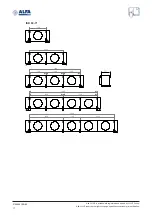
Page 15: ...e specifications without prior notification 800 1600 2400 1600 1600 1600 800 1600 3200 4000 4800 1600 1600 1600 737 5 2 Mounting dimensions Detailed drawings showing all required mounting and refrigerant connection dimensions are available for download on alfa luvegroup com Dimensional drawings Arctigo ISD ISD 40 45S ...

Page 16: ...a trademark registered and owned by LU VE Group Alfa LU VE reserves the right to change specifications without prior notification 1000 2000 2000 2000 2000 1000 2000 1000 1000 1000 2000 2000 2000 6000 5000 4000 3000 737 ISD 45 50 63S ...

Page 17: ...fa LU VE is a trademark registered and owned by LU VE Group Alfa LU VE reserves the right to change specifications without prior notification 1200 2400 2400 2400 2400 1200 2400 1200 1200 1200 3600 4800 6000 737 ISD 63 71 ...

Page 18: ... LU VE is a trademark registered and owned by LU VE Group Alfa LU VE reserves the right to change specifications without prior notification 1600 1600 1600 1600 1600 1600 1600 1600 1600 1600 3200 4800 6400 737 ISD 80 91 91S ...

Page 19: ...iling Avoid any lateral torque on the mounting brack ets 5 4 Technical spaces The following guidelines are to be respected when positioning air cooler units Minimum wall distance on suction side Minimum space for defrost heater replacement optional Side for defrost elements extraction is opposite to the connections Adequate spacing for driptray opening shall be left below the cooler D Hcoil D Hcoi...

Page 20: ...local Alfa LU VE representative for assistance 5 5 Drain line The drain line diameter must be at least the size of the driptray drain diameter and should be laid with an adequate slope For room temperatures below 0 C drain line insulation and an internal or external heating element are required to prevent freezing Tighten drain connection by using two wrenches Keep wrenches firmly to not strain on...

Page 21: ...s OUT hot gas IN from driptray if connected in series hot gas IN from driptray if connected in series hot gas OUT driptray OUT driptray IN driptray IN hot gas OUT driptray OUT hot gas IN from driptray if connected in series driptray IN hot gas OUT driptray OUT hot gas IN from driptray if connected in series ISB pumped bottom feed ISB direct expansion ISD pumped bottom feed ISD direct expansion hot...

Page 22: ...IN driptray OUT hot gas IN from driptray if connected in series hot gas OUT driptray IN driptray OUT hot gas OUT hot gas IN from driptray if connected in series ISB pumped bottom feed 4 connections ISD pumped bottom feed 4 connections driptray IN driptray OUT hot gas OUT hot gas IN from driptray if connected in series driptray IN driptray OUT hot gas IN from driptray if connected in series hot gas...

Page 23: ... Top header Connection tube from HG serpentine ISB pumped bottom feed Header DX Connection tube from HG serpentine ISB ISD direct expansion If driptray and coil defrost are connected in series we recommend that hot gas passes first trough the driptray Connection as below are recommended to avoid liquid recirculation 5 8 Hot gas and hot water connection Standardized connection diameters are Ø 35 mm...

Page 24: ... maintenance activity and always follow guidelines and instructions as given in the air cooler product manual AHE00042 6 1 Fan replacement Cable glands must be positioned downwards Use an anti corrosion coating like Geomet or comparable when remounting using new fixing bolts 6 2 Driptray Always disconnect drain line before opening the driptray To open driptray first loosen and remove fixing bolts ...

Page 25: ...nd owned by LU VE Group Alfa LU VE reserves the right to change specifications without prior notification max 90 Push the driptray till the end of hinges Completely lower the driptray Respect the maximum opening angle to avoid damage to the driptray hinges ...

Page 26: ...ter elements always disconnect power supply ensure heaters are at ambient temperature To remove heater elements remove the fixing screw and the plate if any Extract element from coil Mount new element in reverse order and restore electrical connections 6 5 Driptray heater elements replacement optional Before handling heater elements always disconnect power supply ensure heaters are at ambient temp...

Page 27: ... 6 6 Shut up sock mounting optional When shut up sock option is selected shut up ring is supplied assembled Position the shut up sock such that the belt is mechanically blocked by the rounding on the sock ring Slacken the shut upsock belt Let the sock over lap the sock ring Fasten the belt Fasten again the belt tighter Test tightness to verify correct mounting ...

Page 28: ...E reserves the right to change specifications without prior notification 6 7 Suction hoods mounting optional Suction hoods shall be assembled before mounting the unit to the ceiling Place the suction hoods on air inlet side coil side Place 2 screws per side Slot the screws into the sockets ...

Page 29: ...31466441EN 00 29 Alfa LU VE is a trademark registered and owned by LU VE Group Alfa LU VE reserves the right to change specifications without prior notification Tighten the 2 screws per side ...

Page 30: ...a LU VE reserves the right to change specifications without prior notification 7 Spare parts Spare parts Side panel Fan motor Fan ring heater FRH Defrost heater identical for coil and driptray Driptray Contact your local Alfa LU VE representative for spare parts order and assistance ...

Page 31: ......

Page 32: ...alfa luvegroup com ...

Reviews: