background image

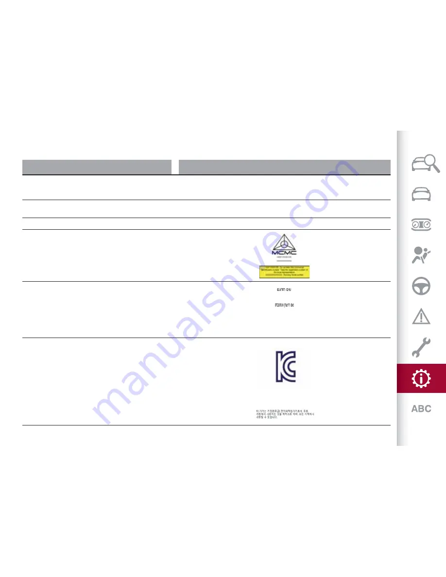
OFFICIAL TYPE APPROVALS FOR SPECIFIC MARKETS

Country

FOBIK system type approval code

Benin

AGREE PAR L’ATRPT BENIN

Numéro d’agrément : MR nnnn ANRT nnnn

Date d’agrément : nnnnnn

Botswana

BOCRA

REGISTERED NO: nnnnnn

Ghana

NCA APPROVED: 3R8-8M-7DF-28D

Malaysia

Israel

ALFA434

Continental Automotive GmbH

Siemensstrasse 12

93055 Regensburg

Germany

South Korea

MSIP-CRM-TAL-ALFA434

Continental Automotive GmbH

FOBIK

ALFA434

281

Summary of Contents for Giulia 952 2017

Page 1: ...OWNER HANDBOOK ...

Page 2: ......

Page 3: ... all with those concerning brakes steering and gearbox at the same time you can understand the vehicle behaviour on different road surfaces This document also provides a description of special features and tips as well as essential information for the safe driving care and maintenance of your Alfa Romeo over time After reading it you are advised to keep the handbook inside the vehicle for an easy ...

Page 4: ...e button PARKING ON FLAMMABLE MATERIAL The catalytic converter develops high temperatures during operation Do not park the car on grass dry leaves pine needles or other flammable material fire hazard RESPECTING THE ENVIRONMENT The vehicle is fitted with a system that carries out a continuous diagnosis of the emission related components in order to help protect the environment ELECTRICAL ACCESSORIE...

Page 5: ...g obstructs the pedal stroke mats etc Alfa Romeo S p A shall not be liable for damage caused by the installation of accessories either not supplied or recommended by Alfa Romeo S p A and or not installed in compliance with the provided instructions INSTALLING ELECTRICAL ELECTRONIC DEVICES Electrical and electronic devices installed after buying the car in the context of after sales service must ca...

Page 6: ...nes is concerned GSM GPRS UMTS LTE follow the usage instructions provided by the mobile phone Manufacturer IMPORTANTThe use of these devices inside the passenger compartment without an external aerial may cause the electrical systems to malfunction This could compromise the safety of the car in addition to constituting a potential hazard for passengers health IMPORTANT If mobile phones laptops sma...

Page 7: ...at the end of this Owner Handbook Chapters can be rapidly identified with dedicated graphic tabs at the side of each odd page A few pages further there is a key for getting to know the chapter order and the relevant symbols in the tabs There is in any case a textual indication of the current chapter at the side of each even page WARNINGS AND PRECAUTIONS While reading this Owner Handbook you will f...

Page 8: ...production of the model outside the specific request of options at the time of purchase will be identified with the wording where provided All data contained in this publication are intended to help you use your vehicle in the best possible way Alfa Romeo S p A aims at a constant improvement of the vehicles produced For this reason it reserves the right to make changes to the model described for t...

Page 9: ...ng the contents herein Always take great care to all warnings herein READTHE USER S MANUAL DO NOTTOUCHWITH HANDS ITCAN START AUTOMATICALLYALSO WITH ENGINE OFF PROTECTYOUR EYES DO NOTOPENTHE CAP WHENTHE ENGINE IS HOT DO NOTOPEN HIGH PRESSURE GAS KEEP CHILDREN ATA DISTANCE BURSTING MOVING PARTS KEEP PARTS OF YOUR BODYAND CLOTHES AWAY DO NOTAPPROACH FLAMES CORROSIVE LIQUID HIGHVOLTAGE ...

Page 10: ...This page is intentionally left blank ...

Page 11: ...GRAPHICAL INDEX KNOWING YOUR CAR KNOWINGTHE INSTRUMENTPANEL SAFETY STARTING AND DRIVING IN AN EMERGENCY SERVICING AND CARE TECHNICAL DATA INDEX ...

Page 12: ......

Page 13: ...7 Bulb replacement 189 WHEELS Rims and tyres provided 256 Tyre pressure 258 Tire Repair Kit 198 DOOR MIRRORS Adjustment 38 DOORS Central opening closing 25 CHECKING LEVELS Checking levels 220 WINDSCREENWIPERS Operation 46 1 03016S0001EM 11 ...

Page 14: ...ulbs 187 Bulb replacement 189 WHEELS Rims and tyres 256 Tyre pressure 258 Tire Repair Kit 198 DOOR MIRRORS Adjustment 38 DOORS Central opening closing 25 CHECKING LEVELS Checking levels 220 WINDSCREENWIPERS Operation 46 2 03016S0002EM 12 GRAPHICAL INDEX ...

Page 15: ...REAR VIEW REAR LIGHTS External lights 39 BOOT Opening closing 58 3 03026S0001EM 13 ...

Page 16: ...REAR VIEW QUADRIFOGLIO VERSION REAR LIGHTS External lights 39 BOOT Opening closing 58 4 03026S0002EM 14 GRAPHICAL INDEX ...

Page 17: ...ators 42 CONTROLS ON STEERINGWHEEL Cruise Control 159 INSTRUMENTPANEL Control panel and on board instruments 68 STEERINGWHEEL Adjustments 36 Front airbags 134 RIGHTSTALK Window washing 46 CONNECT CLIMATE CONTROL SYSTEM Automatic dual zone climate control system 49 GLOVE COMPARTMENT 60 PASSENGER SIDE AIR BAG 136 5 03036S0001EM 15 ...

Page 18: ...ers 3 Left stalk 4 Steering wheel controls 5 Instrument panel 6 Steering wheel 7 Right stalk 8 Connect 9 Automatic dual zone climate control system 10 Glove compartment 11 Passenger side air bag 12 Bonnet release lever 6 03036S0020EM 16 GRAPHICAL INDEX ...

Page 19: ...CWINDOWS ELECTRIC DOOR MIRRORS Electric windows 55 Electric door mirrors control 38 GEARBOX TRANSMISSION Using the transmission 147 Using the manual gearbox 146 HAZARDWARNING LIGHTS Operation 186 Alfa DNA Pro SYSTEM Operation 152 7 03046S0001EM 17 ...

Page 20: ...This page is intentionally left blank ...

Page 21: ...ely what is described here for yourself KNOWING YOUR CAR THE KEYS 20 IGNITION DEVICE 22 ENGINE IMMOBILIZER 23 ALARM SYSTEM 24 DOORS 25 SEATS 30 HEADRESTS 35 STEERINGWHEEL 36 REARVIEWMIRRORS 37 EXTERNAL LIGHTS 39 INTERIOR LIGHTS 43 WINDSCREENWIPER 46 CLIMATE CONTROL 48 WINDOWWINDERS 55 ELECTRIC SUNROOF 56 BONNET 57 LUGGAGE COMPARTMENT 58 INTERIOR FITTINGS 60 ROOF RACK SKI RACK 64 ENVIRONMENTAL PROT...

Page 22: ...ocking the doors For further information see paragraph Settings in the Connect booklet The doors can always be unlocked by putting the metal insert inside the driver side door lock Door and boot lock Briefly press the button locking of doors and boot timed switching off of internal lights and double flashing of direction indicators if activated from Connect system If one or more doors are open the...

Page 23: ...car s electronics If an electronic key is coded for a car it cannot be used on any other car Duplicating keys If you need a new electronic key go to an Alfa Romeo Dealership taking an ID document and the car ownership documents IMPORTANT 1 The electronic components inside the key may be damaged if the key is subjected to strong shocks In order to ensure complete efficiency of the electronic device...

Page 24: ...pass and the engine stopped the ignition device will automatically move to the STOP position NOTE With the engine running it is possible to go away from the car taking the electronic key with you The engine will still be running The vehicle will indicate the absence of the key on board when the door is closed For more information on the engine start up see the description in the Starting the engin...

Page 25: ... the car or in a place accessible to children Do not leave the vehicle with the ignition device in ON position A child could activate the electric window winders other controls or even start the vehicle 5 If the ignition device has been tampered with e g an attempted theft have it checked over by the Alfa Romeo Dealership before driving again ENGINE IMMOBILIZER The Engine Immobilizer system preven...

Page 26: ...tion of the alarm triggers the acoustic warning and the direction indicators IMPORTANTThe function is ensured by the Engine Immobilizer system which is automatically activated when you get out of the vehicle taking the electronic key with you and locking the doors IMPORTANTThe alarm is adapted to meet requirements in various countries SWITCHING ONTHE ALARM With the doors bonnet and tailgate closed...

Page 27: ...D on the button flashing for several seconds Any disabling of the volume sensing anti lift protection must be repeated each time the instrument panel is switched off DISABLINGTHE ALARM To completely disable the alarm e g during a long period of car inactivity lock the doors by turning the metal insert found inside the electronic key in the door lock DOORS LOCKING UNLOCKING DOORS FROM THE INSIDE Ce...

Page 28: ...f it has rained and the door handle is wet the activation sensitivity of the Passive Entry function may be reduced resulting in a longer reaction time Door locking To lock the doors proceed as follows make sure that you have the electronic key and are close to the driver or passenger side door handle press the door locking button fig 18 located on the handle or the button fig 19 on the tailgate ne...

Page 29: ...ing button fig 22 on the front door handles or button in the door panel inner trim fig 23 is pressed a check of the inside and outside of the car for the presence of active electronic keys is made once all the open doors are closed Pulling the handle do not press the door lock unlock button fig 22 on the handle fig 24 If one of the electronic keys is detected inside the car and no other active ele...

Page 30: ... still be locked by pressing the button on the electronic key or by pressing the door lock button on the external handles or by pressing the button on the inner door panel of the vehicle On cars equipped with Passive Entry the boot lid and the doors can be locked by pressing the fig 26 button located near the opening button on the boot lid System activation deactivation The Passive entry system ca...

Page 31: ...ed press the button on the electronic key press the button on the door panel open by inserting the key insert in the driver s door lock operate the internal door handle IMPORTANT For the rear doors if the child lock device was engaged and the previously described locking procedure carried out operating the internal handle will not open the door but will only realign the lock release device To open...

Page 32: ...upants Driver seat adjustment must also be carried out remembering that keeping the shoulders resting firmly against the backrest the wrists must be able to reach the top of the steering wheel rim Additionally it must be possible to depress the clutch pedal with the left foot for versions with manual gearbox or fully depress the brake pedal with the right foot FRONTSEATS WITH MANUAL ADJUSTMENT 9 4...

Page 33: ...e angle of the seat cushion Longitudinal adjustment Push switch 1 fig 31 forwards or backwards to move the seat in the corresponding direction Backrest angle adjustment Push switch 2 fig 31 forwards or backwards to adjust the backrest in the corresponding direction Electric lumbar adjustment Use the joystick 3 to operate the lumbar area device to obtain the right comfort while driving Press the fo...

Page 34: ...s after the doors are opened and about 1 minute after the engine is stopped To recall a memorised position press the relevant button briefly EASY ENTRY FUNCTION The Easy Entry function is designed to retract the driver side seat automatically by 2 36 in 60 mm to make it easier for the driver to get in and out of the car The movement is activated only if the seat is set to a driving position which ...

Page 35: ...When the maximum heating setting is selected the heater produces a boosted heat level for the first minutes of operation After this the heat lowers to reach the normal temperature level for the selected function The same minimum heating setting is automatically deactivated once a certain period of time has elapsed This varies on a case by case basis in accordance with the specific operating condit...

Page 36: ...he backrest while tilting it use levers 1 and 2 to fold down the backrests these will fold down forwards automatically If necessary accompany the backrests during the initial stage of tilting Repositioning the backrests Move the seatbelts to the side making sure that they are correctly extended and not twisted and that they are not trapped behind the backrests of the seats then lift the backrests ...

Page 37: ...ry of the seats has been designed to withstand long term wear deriving from normal use of the car Some precautions are however required Avoid prolonged and or excessive rubbing against clothing accessories such as metal buckles andVelcro strips which by applying a high pressure on the fabric in a small area could cause it to break thereby damaging the upholstery 5 Do not place any kind of items un...

Page 38: ...and 2 fig 41 rear head restraints at the side of the two supports then remove the head restraints by pulling them upwards IMPORTANT Always re position the rear head restraints if they had been removed before starting to drive normally Re fit the rods of the head restraints in their housings holding buttons 1 and 2 pressed Then re position the head restraints according to your needs WARNING 13 Head...

Page 39: ...un down WARNING 14 All adjustments must be carried out only with the car stationary and engine stopped 15 It is absolutely forbidden to carry out any after market operation involving steering system or steering column modifications e g installation of anti theft device that could adversely affect performance invalidate the warranty cause SERIOUS SAFETYPROBLEMS and also result in the car not meetin...

Page 40: ...the device 1 again to position C to return the mirrors to the driving position If device 1 is turned again during door mirror folding from closed to open position and vice versa their movement direction is reversed Automatic activation Activating the central door locking system from outside the car automatically folds the mirrors they return to the driving position when the ignition device is turn...

Page 41: ... for adjusting the headlight alignment where fitted 6 rear fog lights button 7 Start Stop Evo function deactivation button The external lights can be activated only when the ignition device is in position ON except for the parking lights See the Parking lights paragraph in this chapter for more information The instrument panel and the various controls on the dashboard will be lit up when the exter...

Page 42: ... better by lighting the corresponding fog light The cornering function can be deactivated on the Connect system by selecting the following functions in sequence on the main menu Settings Lights and Cornering Lights REAR FOG LIGHT The rear fog light switch is integrated with the light switch Press the button to switch the light on off The rear fog light switches on only when the dipped beam headlig...

Page 43: ...le you are operating the lever Automatic high beam headlights where provided In order not to dazzle other road users the lights are automatically deactivated when approaching cars travelling in the opposite direction or when following a car travelling in the same direction This function is enabled with the Connect system and with the light switch turned to AUTO When the high beam headlights are op...

Page 44: ...h and the steering radius is below 0 3 mi 500 m HEADLIGHTALIGNMENTADJUSTMENT Light beam direction The correct aiming of the headlights is important for the comfort and safety of not only the driver but all other road users This is also covered by a specific rule of the highway code The headlights must be correctly aligned to guarantee the best visibility conditions for all drivers while travelling...

Page 45: ...eiling light 6 7 8 switching on off upon opening closing the doors Lights switch on off progressively Switch 5 switches on off light 6 IMPORTANT Before getting out of the vehicle make sure that the ceiling light bulbs are off this will prevent the battery level from being uselessly drained once the doors are closed In any case if a light is left on by mistake the ceiling light switches off automat...

Page 46: ...ment is opened and switches off when it is closed The light switches on off regardless of the ignition device status INTERIOR AMBIENTLIGHTING The brightness of the interior passenger compartment lights can be adjusted through the Connect system To access the adjustment function on the main menu select the following items in sequence Settings Lights and Interior Ambient Lighting The brightness can ...

Page 47: ...e switch on automatically when the boot is opened and switch off when it is closed The roof lights switch on off regardless of the position of the ignition switch If the boot is left open the lights will automatically switch off after 15 minutes to preserve the battery life INSTRUMENTPANEL AND CONTROL BUTTON GRAPHIC BRIGHTNESS ADJUSTMENT With side lights or headlights on operate on the ring nut fi...

Page 48: ...deposits of dust from the windscreen or morning dew IMPORTANTThis function does not activate the windscreen washer windscreen washer fluid will not therefore be sprayed onto the windscreen To spray windscreen washer fluid onto the windscreen the washing function must be used With ring nut in position or the windscreen wiper will automatically adapt its operating speed to the speed of the vehicle R...

Page 49: ...gardless of whether there is rain on the glass while sensor failure is indicated on the display The sensor continues to operate and it is possible to set the windscreen wiper to continuous mode or The failure indication remains for as long as the sensor is active The rain sensor is able to recognise and automatically adjust itself in the presence of the following conditions presence of dirt on the...

Page 50: ...t the air flow Central air diffusers 1 fig 62 Adjustable central air diffusers use device 2 to adjust the diffuser to the desired position turn ring nut 3 to adjust the air flow 4 Windscreen air vent Rear air diffusers 1 fig 63 Adjustable rear air diffusers use ring nut 2 to adjust the diffuser to the desired position turn ring nut 2 to adjust the air flow 61 04156S0002EM 62 04156S0003EM 63 04156S...

Page 51: ...ion selection button 8 Passenger side AUTO function activation button automatic operation 9 Passenger side temperature adjustment knob 10 SYNC function button set temperature alignment driver passenger side 11 Passenger side seat heater activation button where provided see chapter on seats 12 Climate control compressor on off button 13 Steering wheel heater activation button where provided see cha...

Page 52: ... conditions when the compressor is not running The system allows the following to be set or adjusted manually driver passenger side air temperature fan speed continuous variation driver and passenger air distribution to 7 positions compressor enabling rapid defrosting demisting function air recirculation heated rear window system deactivation Operating mode of the climate control system The climat...

Page 53: ...ng allows the passenger compartment to be warmed up efficiently and prevents the windows from misting up Air flow distribution between windscreen demisting defrosting vents and side and central dashboard vents This allows air to be sent to the windscreen in conditions of strong sunlight Air flow distribution to all diffusers on the vehicle In AUTO mode the air conditioner automatically manages the...

Page 54: ...em enables a few cycles of outside air intake to change the air in the passenger compartment for a preset time The AQS function is disabled during the air changes IMPORTANTThe engagement of the recirculation system makes it possible to reach the required heating cooling conditions faster It is however inadvisable to use it on rainy cold days as it would considerably increase the possibility of the...

Page 55: ...unction switches off automatically after about 20 minutes or when the engine is turned off It is not switched on automatically the next time the engine is started IMPORTANT Do not apply stickers to the inside of the heated rear window over the heating filaments to avoid damage that might cause them to stop working properly Humidity sensor The humidity sensor helps to prevent the windows from misti...

Page 56: ...f the Stop Start Evo to prevent the compressor from continuously switching on and off with consequent rapid misting of the windows and accumulation of humidity with unpleasant smells in the passenger compartment When the Start Stop Evo is on engine off and vehicle at a standstill the automatic recirculation management may be turned off to prevent the windows misting up always taking air in from ou...

Page 57: ...the desired position Window closing Lift the buttons to close the desired window The window closing stage occurs following the same logic described for the opening stage both of the front door windows and the rear door windows Passenger side front door rear door controls On the door control panel buttons are provided to control the associated windows Window anti pinch safety device The vehicle is ...

Page 58: ...l on button 1 fig 68 the roof will open to the comfort position A second press will open it fully A long press of the same button will open the roof until it is released or if held down until it reaches the comfort position Use the button in the same way to open the roof fully from that position 11 The automatic motion can be interrupted in any position by pressing button 1 again If the electric b...

Page 59: ...er 10 seconds you will hear the electric motors of the roof and blind stop in sequence release the button and within 5 seconds press the symbol on button 1 and hold it down until the cycle end the roof will automatically perform a complete open and close cycle to indicate that the initialisation has been successful If this does not occur the procedure must be restarted from the beginning WARNING 2...

Page 60: ... must check that it is closed on both its side ends WARNING 22 Perform these operations only when the car is stationary 23 Use both hands to lift the bonnet Before lifting check that the windscreen wiper arms are not raised from the windscreen or in operation that the vehicle is stationary and that the electric parking brake is engaged 24 For safety reasons the bonnet must always be properly close...

Page 61: ...e manual tailgate opening strap before disconnecting the battery The procedure is described in the Prolonged car inactivity paragraph in the Maintenance and Care chapter IMPORTANTThis procedure must be carried out exclusively in safe places because it allows to open the boot unconditionally BOOTINITIALISATION IMPORTANT If the battery is disconnected or the protection fuse blows the boot opening cl...

Page 62: ...ert in the key into the lock operate handle fig 77 to open the compartment Air conditioned storage compartment where provided The compartment may be cooled in some versions by means of an air vent connected to the air conditioning system To regulate the air flow in the compartment adjust wheel 1 fig 78 Wheel turned clockwise cooling open wheel turned anticlockwise cooling closed The air temperatur...

Page 63: ...ing the engine Proceed as follows press and hold the outer buttons 1 and 3 fig 80 after about 10 seconds the LED 4 will start to flash then release both buttons NOTE This operation is designed to delete the standard codes programmed by the manufacturer This operation does not have to be repeated during the subsequent button programming press the desired HomeLink button 1 2 or 3 when the HomeLink L...

Page 64: ...y 1 2 or 3 and release it Press the programmed button a second time and release it to conclude the operation For some motors the operation will probably have to be repeated a third time to end the setting The motor should now be capable of recognizing the signal transmitted by the HomeLink and then open close the door or gate PROGRAMMING A SINGLE KEY It is possible to program another original remo...

Page 65: ...n international call POWER SOCKET It is located inside the storage compartment on the central tunnel fig 81 It only operates with the ignition device at ON IMPORTANT Do not connect devices with power higher than 180 Wto the socket Do not damage the socket by using unsuitable adaptors FRONTARMREST This is located between the front seats There is a storage compartment inside the armrest operate devi...

Page 66: ... may catch fire in contact with cigarette stubs ROOF RACK SKI RACK The attachments 1 fig 85 are located in the areas illustrated in the figure and can only be accessed with the doors open 28 29 13 14 Lineaccessori Alfa Romeo includes a dedicated roof rack ski rack for this vehicle WARNING 28 After travelling for a few kilometres check to ensure that the fixing screws for the attachments are well t...

Page 67: ...ion procedure is controlled automatically by the engine management control unit according to the filter conditions and vehicle use conditions During the regeneration there may be a limited increase in the engine idle speed fan activation a limited increase in fumes and high temperatures at the exhaust These are not faults they do not impair normal vehicle performance or damage the environment If t...

Page 68: ...This page is intentionally left blank ...

Page 69: ... the information you need to understand interpret and use the instrument panel correctly KNOWINGTHE INSTRUMENTPANEL CONTROL PANEL AND ON BOARD INSTRUMENTS 68 DISPLAY 72 WARNING LIGHTS AND MESSAGES 79 EOBD SYSTEM European On Board Diagnosis 103 ...

Page 70: ... Digital engine oil temperature gauge with overheating warning light 3 TFTDisplay 4 Digital fuel level gauge the triangle on the left side of the symbol indicates the side of the vehicle with the fuel filler 5 Speedometer speed indicator 87 05026S0001EM 68 KNOWING THE INSTRUMENT PANEL ...

Page 71: ...Rev counter 2 Digital engine oil temperature gauge with overheating warning light 3 TFTDisplay 4 Digital fuel level gauge the triangle on the left side of the symbol indicates the side of the vehicle with the fuel filler 5 Speedometer speed indicator ...

Page 72: ...re gauge with overheating warning light 3 TFTDisplay 4 Digital fuel level gauge the triangle on the left side of the symbol indicates the side of the vehicle with the fuel filler 5 Speedometer speed indicator 89 05026S0004EM 70 KNOWING THE INSTRUMENT PANEL ...

Page 73: ...the scale according to the working conditions The warning lights switches on to signal the excessive increase of the engine oil temperature In this case immediately stop the engine and contact an Alfa Romeo Dealership FUEL LEVEL GAUGE The bar digital gauge monitors the amount of fuel in the tank The warning light turns on a message is displayed and an acoustic warning is emitted when about 1 8 UK ...

Page 74: ...the display is divided into multiple sections which show driving data warnings and failure indications fig 90 shows the display layout identifying the various sections 1 Gearbox information 2 Front side anti collision systems Cruise Control 3 Speed limit warning light 4 Reconfigurable main area 5 Compass 6 Odometer 7 Failure warning lights 8 Range 7 TFTDisplay only 9 Warning lights 7 TFTDisplay on...

Page 75: ...lay the following screens Home Trip A Trip B can be activated deactivated on the Connect system Performance The screens can be selected on rotation by pressing the button shown in fig 91 Depending on the chosen driving mode Dynamic Normal Advanced Efficiency and RACE which can be selected through the Alfa DNA Pro system the screens can be graphically different The navigation instructions and call ...

Page 76: ...and RACE and with the ignition device ON the measurements regarding the operating state of the car This function is characterised by two separate records called Trip A and Trip B the latter can be deactivated by Connect system where the car s complete missions journeys are recorded in a reciprocally independent manner Trip A and Trip B are used to display the values relating to Distance travelled ...

Page 77: ...the driving style with a view to limiting consumption Advanced Efficiency 3 5 TFTDisplay 7 TFTDisplay The three central icons on the screen indicate the effectiveness of the driving style linked to the following parameters acceleration deceleration and gear shifts with a view to limiting consumption The bar below the icons shows current consumption and the green line represents the optimal area Th...

Page 78: ...ravelled 7 anomaly warning lights Area dedicated to displaying failures the following symbols could be displayed on rotation Low criticality symbols yellow amber High criticality symbols red 8 Range 7 TFT Display only Indicates the kilometres or miles left before the fuel tank is empty 9 Warning lights 7 TFT Display only Displays the warning light related to the active mode among the following dip...

Page 79: ...he factory settings To access and adjust the various settings turn and press the Rotary Pad to select and confirm the selection Time and Date The following settings can be modified when this mode is selected fig 109 Sync with GPSTime activates deactivates the clock synchronization through the GPS if the function is deactivated the options SetTime and Set Date are enabled Set time allows to manuall...

Page 80: ...well Audio repeat allows to activate deactivate the repetition of the audio Radio and Media function screens on the instrument panel display as well Nav repeat allows to activate deactivate the repetition of the audio Radio and Media function screens on the instrument panel display as well Restore Settings deletes the current settings and restores the factory settings To access and adjust the vari...

Page 81: ...ses In the event of a failure indication always refer to the contents of this chapter IMPORTANTThe failure indicators appearing on the display are divided into two categories very serious and less serious faults Serious faults are indicated by a repeated and prolonged warning cycle Less serious faults are indicated by a warning cycle with a shorter duration You can stop the warning cycle in both c...

Page 82: ...ng light switches on when the electric parking brake is engaged IMPORTANTIf the car is parked on a gradient of more than 30 and or the temperature of the brakes is greater than 662 F 350 C when the parking brake is engaged the warning light will flash to indicate a potentially unsafe condition Release the electric parking brake then check that the warning light has switched off If the warning ligh...

Page 83: ...light switches on in the case of engine oil overheating 15 If the problem persists contact an Alfa Romeo Dealership WARNING 31 The fault of the warning light is signalled by the switching on of the icon on the instrument panel In this case the warning light may not indicate any faults with the restraint systems Before proceeding contact an Alfa Romeo Dealership to have the system checked immediate...

Page 84: ...ot continue driving with one or more flat tyres as handling may be compromised Stop the vehicle avoiding sharp braking and steering Immediately restore the correct inflation pressure using theTire Repair Kit see Repairing a wheel paragraph in the In an emergency chapter and contact the dedicated Alfa Romeo Dealership as soon as possible Tyre pressure low The warning light switches on to indicate t...

Page 85: ... In these cases contact an Alfa Romeo Dealership as soon as possible Hill Start Assist system failure the switching on of the warning light indicates a Hill Start Assist system failure PARTIAL TOTAL DEACTIVATION OF ACTIVE SAFETY SYSTEMS where provided When the ignition device is brought to ON the warning light switches on but should switch off as soon as the engine is started The warning light swi...

Page 86: ...ppears but is still stored by the system Under these conditions the vehicle can continue travelling at moderate speed but without demanding excessive effort from the engine or high speed Prolonged use of the car with the warning light on constantly may cause damage Contact an Alfa Romeo Dealership as soon as possible Catalytic converter damaged If the warning light flashes it means that the cataly...

Page 87: ...river that the frontal collision alarm function is not enabled FUEL RESERVE LIMITED RANGE The warning light or the icon on the display turns on when there are about 1 8 UK gal 8 litres of fuel left in the tank for Diesel versions and about 2 UK gal 9 litres of fuel for petrol versions 33 WARNING 33 If the warning light or the icon on the display flashes whilst driving contact an Alfa Romeo Dealers...

Page 88: ...ights are turned on LEFTDIRECTION INDICATOR The warning light switches on when the direction indicator control stalk is moved downwards or together with the right direction indicator when the hazard warning light button is pressed RIGHTDIRECTION INDICATOR The warning light switches on when the direction indicator control stalk is moved upwards or together with the left direction indicator when the...

Page 89: ...Blue warning lights Warning light What it means What to do MAIN BEAM HEADLIGHTS on 3 5 TFTdisplay The symbol comes on when the main beam headlights are activated 87 ...

Page 90: ...t level if necessary If the symbol turns on continuously contact an Alfa Romeo Dealership to have the system checked WARNING IFTHE SYMBOLTURNS ON CONTINUOUSLY Do not use the car until the failure has been solved When the symbol turns on it does not indicate the amount of oil in the engine the oil level can be checked on the display upon entering the vehicle and also by activating the Oil level fun...

Page 91: ...n stop the vehicle Stop for 2 or 3 minutes with the engine running and slightly accelerated to facilitate better coolant circulation then turn the engine off Check that the coolant level is correct as described above POWER STEERING FAILURE If the symbol remains on you could not have steering assistance and the effort required to operate the steering wheel could be increased steering is however pos...

Page 92: ... damage the gearbox with resulting breakage The oil may also overheat contact with hot engine or with exhaust components at high temperature could cause fires Symbol What it means What to do INSUFFICIENTENGINE OIL LEVEL The symbol switches on along with the related message on the display to indicate low engine oil level On the QVversion the level must also be checked using the dipstick below the b...

Page 93: ... an Alfa Romeo Dealership as soon as possible ALFA SYSTEM STEERINGTORQUE AST FAILURE The switching on of the symbol signals a failure in the automatic steering correction system Contact an Alfa Romeo Dealership to have the system checked SPEED LIMITEXCEEDED where provided The symbol switches on when the speed limit of 74 5 mph 120 km h is exceeded 91 ...

Page 94: ...ey is not recognized by the system Alarm system failure This symbol switches on to report an alarm system failure FUEL CUT OFF SYSTEM OPERATION The symbol switches on in the event of fuel cut off system intervention For reactivating the fuel cut off system refer to the description in the Fuel cut off system section in the In an emergency chapter If it is not possible to restore the fuel supply con...

Page 95: ...soon as possible after the symbol is switched on and never more than 500 km after it first switches on Failure to observe the above may result in severe damage to the engine and invalidate the warranty When this symbol comes on it does not mean that the level of engine oil is low so if it flashes you do not need to top up the engine oil Symbol What it means What to do GLOWPLUG PREHEATING Diesel ve...

Page 96: ...es on to report a Stop Start Evo system failure Contact an Alfa Romeo Dealership as soon as possible to have the failure eliminated RAIN SENSOR FAILURE The symbol switches on in the case of failure of the automatic windscreen wiper Contact an Alfa Romeo Dealership as soon as possible DUSK SENSOR FAILURE The symbol switches on in the case of failure of the automatic low beam alignment Contact an Al...

Page 97: ... of Keyless Start system failure Contact an Alfa Romeo Dealership as soon as possible FUEL CUT OFF SYSTEM FAILURE The symbol switches on in the event of fuel cut off system failure Contact an Alfa Romeo Dealership as soon as possible LANE DEPARTUREWARNING SYSTEM LDW FAILURE The symbol comes on in the event of a failure in the Lane DepartureWarning system Contact an Alfa Romeo Dealership as soon as...

Page 98: ...t the DPF system needs to eliminate the trapped pollutants particulate through the regeneration process The symbol does not switch on during every DPF regeneration but only when driving conditions require that the driver is notified To turn off the symbol keep the car in motion until the regeneration process is over On average the process lasts 15 minutes Optimal conditions for completing the proc...

Page 99: ...ontact an Alfa Romeo Dealership as soon as possible to have the failure eliminated FUELTANK PLUG where provided The symbol lights up if the fuel tank cap is open or not properly closed Tighten the cap properly ELECTRIC PARKING BRAKE FAILURE The symbol and the the respective message appear on the display to indicate a failure in the electric parking brake system This failure could partially or comp...

Page 100: ...PADS The symbol lights up when the brake pads have reached their wear limit Contact an Alfa Romeo Dealership as soon as possible IMPORTANTAlways use genuine parts or equivalents because the Integrated Brake System IBS system could detect anomalies WEAR ON CCB BRAKE DISCS where provided The symbol will light up when the carbon ceramic brake discs have reached the limit of wear Contact an Alfa Romeo...

Page 101: ...tches on to report a four wheel drive system failure Contact an Alfa Romeo Dealership as soon as possible to have the failure eliminated AFS SYSTEM FAILURE If this symbol appears it indicates a failure of the automatic directional headlight system Go to an Alfa Romeo Dealership to have the system checked SOFTSUSPENSION CALIBRATION INSERTION where provided The system appears when the most comfortab...

Page 102: ...HER LIQUID LEVEL The symbol appears for some seconds to indicate that the level of the windscreen and headlight washing fluid if any is low Refill the liquid to do this please consult the Level check section in the Service and care chapter Always use liquid with the features indicated in the Liquids and lubricants section in the Technical information chapter 100 KNOWING THE INSTRUMENT PANEL ...

Page 103: ...e on START STOP EVO OPERATION The symbol comes on in the case of Start Stop Evo system intervention stopping the engine When the engine is restarted the symbol switches off for the engine restarting modes see the Start Stop Evo paragraph in the Starting and driving chapter CRUISE CONTROL SYSTEM The symbol comes on when the Cruise Control system is activated ACTIVE CRUISE CONTROL SYSTEM The symbol ...

Page 104: ...MATIC HIGH BEAM HEADLIGHTS on 7 TFT display The symbol comes on when the automatic main beam headlights are activated MAIN BEAM HEADLIGHTS on 7 TFTdisplay The symbol comes on when the main beam headlights are activated 102 KNOWING THE INSTRUMENT PANEL ...

Page 105: ... On Board Diagnosis is to monitor the efficiency of the system indicate an increase in emissions indicate the need to replace damaged components The vehicle also has a connector which can interface with appropriate tools that makes it possible to read the error codes stored in the electronic control units together with a series of specific parameters for engine operation and diagnosis This check c...

Page 106: ...This page is intentionally left blank ...

Page 107: ... vehicle is equipped and provides instructions on how to use them correctly SAFETY ACTIVE SAFETYSYSTEMS 106 DRIVING ASSISTANCE SYSTEMS 109 OCCUPANTPROTECTION SYSTEMS 118 SEATBELTS 118 SBA Seat Belt Alert SYSTEM 120 PRETENSIONERS 121 CHILD PROTECTION SYSTEMS 123 SUPPLEMENTARYRESTRAINTSYSTEM SRS AIRBAG 134 ...

Page 108: ... equipped with an automatically activated deactivated four wheel drive system AWD which offers an optimal drive for countless driving conditions and road surfaces The system reduces the slipping of the tyres to a minimum automatically redistributing the torque to the front and rear wheels as needed To maximize fuel savings the vehicle with AWD automatically passes to rear four wheel drive RWD when...

Page 109: ...hich the brake pedal is pressed and consequently applies the optimal brake pressure This can reduce the braking distance the PBA system therefore complements the ABS Maximum assistance from the PBA system is obtained by pressing the brake pedal very quickly In addition the brake pedal should be pressed continuously during braking avoiding intermittent presses to get the most out of the system Do n...

Page 110: ... ABS cannot prevent accidents including those due to excessive speed on corners driving on low grip surfaces or aquaplaning 40 The capability of the ABS must never be tested irresponsibly and dangerously in such a way as to compromise personal safety and the safety of others 41 For the correct operation of the ABS the tyres must of necessity be the same make and type on all wheels in perfect condi...

Page 111: ...gine off and engaged first gear so that it is parked in safe conditions for further information read the Parking paragraph in the Starting and driving chapter 58 There may be situations on small gradients less than 8 with vehicle laden in which the Hill Start Assist system may not activate causing a slight reversing motion and increasing the risk of collision with another vehicle or object The dri...

Page 112: ...cle the system automatically deactivates For the system to operate correctly the rear bumper area where the radar sensors are located must stay free from snow ice and dirt gathered from the road surface Do not cover the rear bumper area where the radar sensors are located with any object e g adhesives bike rack etc If after purchasing the vehicle you wish to install the tow hook you need to deacti...

Page 113: ...3 and a camera located in the middle of the windscreen fig 114 In the event of an imminent collision the system intervenes by automatically braking the car to prevent the impact or reduce its effects The system provides the driver with acoustic and visual signals through specific messages on the instrument panel display The acoustic and visual signals before the system cuts in depend on the car sp...

Page 114: ...s The default option is Med With this setting the system warns the driver of a possible collision with the vehicle in front when that vehicle is at a standard distance between that of the other two settings With the system sensitivity set to Far the system will warn the driver of a possible accident with the vehicle in front when that vehicle is at a greater distance thus providing the possibility...

Page 115: ... performed at an Alfa Romeo Dealership IMPORTANT It is recommended that you do not install devices accessories or aerodynamic attachments in front of the sensor or darken it in any way as this can compromise the correct functioning of the system Frontal collision alarm with active braking where provided Selecting the Warning brake function from the Mode menu on the Connect device allows the FCWsys...

Page 116: ...es travelling at right angles to the vehicle The system could temporarily react to a vehicle that is passing through the radar sensor s operating range at right angles fig 119 Important notes The system has not been designed to prevent impacts and cannot detect possible conditions leading to an accident in advance Failure to take into account this warning may lead to serious or fatal injuries The ...

Page 117: ... on the shoulder of the tyre for further details see the instructions in the Rims and tyres paragraph in the Technical data chapter Tyre pressure increases when the car is driven This is normal and no adjustment of the pressure is required TheTPMS signals the driver a possible insufficient pressure if this falls below the warning limit for any reason including the effects of low temperature and no...

Page 118: ...failure is still resent The warning light switches off when the failure condition disappears and the pressure value is displayed again in place of the dashes A fault in the system could occur in the following cases intense radio frequency interference may prevent the correct operation of the TPMS This condition will be indicated by a dedicated message on the display The warning will disappear auto...

Page 119: ... though it is higher than the prescribed value Repeat the check when the tyres are cold 68 Should one or more wheels be fitted without sensors the system will no longer be available and a warning message will be shown on the display until wheels with sensors are fitted again 69 TheTPMS cannot indicate sudden tyre pressure drops e g if a tyre bursts In this case stop the vehicle braking with cautio...

Page 120: ...ortant safety equipment of the vehicle comprise the following protection systems seat belts SBA Seat Belt Alert System head restraints child restraint systems Front airbags and side bags Read the information given the following pages with the utmost care It is of fundamental importance that the protection systems are used in the correct way to guarantee the maximum possible safety level for the dr...

Page 121: ...the rear seat belts as shown in fig 122 and fig 123 Unlike the side seat belts the central rear one where provided has a double buckle Unwind the belt grasp the fastening tongue 3 fig 122 and introduce it into its housing 4 then insert tongue 2 in housing 1 make sure that both belts are fastened correctly To release tongue 3 press button 5 using either belt fastening tongue 74 WARNING 73 Never pre...

Page 122: ... the warning light turns on constantly The cycle of warnings will be reactivated as soon as the speed exceeds 5 mph 8 km h again REAR SEATBELTICON BEHAVIOUR where provided The icons are shown on the display fig 125 after a few seconds have elapsed since the ignition device is turned to ON and disappear after approximately 30 seconds After a door closes or following a change in belt fastening statu...

Page 123: ...n of the pretensioner which is not harmful and does not involve any fire hazard The pretensioner does not require any maintenance or lubrication any changes to its original conditions will invalidate its efficiency If due to unusual natural events floods sea storms etc the device has been affected by water and or mud contact an Alfa Romeo Dealership to have it replaced IMPORTANTTo obtain the highe...

Page 124: ...ear or cuts WARNING 75 The pretensioner may be used only once After its activation contact an Alfa Romeo Dealership to have it replaced 76 Removing or otherwise tampering with pretensioner and seat belt components is strictly prohibited Any intervention on these components must be performed by qualified and authorised technicians Always contact an Alfa Romeo Dealership 77 For maximum safety keep t...

Page 125: ...ost suitable for the child for this reason always refer to the Owner Handbook provided with the child restraint system to be sure that it is of the right type for the children it is intended for In Europe the characteristics of child restraint systems are ruled by the regulation ECE R44 dividing them into five weight groups Group Weight range Group 0 up to 22 lb 10 kg in weight Group 0 up to 28 7 ...

Page 126: ...rrectly position the child with respect to the seatbelts so the diagonal part of the belt adheres to the thorax and not to the neck and the horizontal part adheres to the child s stomach and not its abdomen Group 3 For children from 48 5 to 79 4 lb 22 to 36 kg there are restraining devices that allow the seatbelts to pass through properly The fig 132 shows the correct child positioning on the rear...

Page 127: ...ht range Front passenger Rear passengers Passenger airbags on Passenger airbags off Rear central passenger where provided Rear side passengers Group 0 up to 22 lb 10 kg X U X U Group 0 up to 26 7 lb 13 kg X U X U Group 1 20 40 lb 9 18 kg X U X U Group 2 33 55 lb 15 25 kg U U X U Group 3 48 5 79 4 lb 22 36 kg U U X U X Restraint system not suitable for children in this weight category U suitable fo...

Page 128: ...ere it meets the backrest then fix the upper hook available with the child restraint system to the dedicated anchor top tether 3 fig 134 located behind the seat headrest As an example fig 135 shows an example of a Universal ISOFIX child restraint system for weight group 1 IMPORTANTThe fig 135 is indicative and for assembly purposes only Fit the child restraint system according to the instructions ...

Page 129: ...rom 33 to 55 lb from 15 kg to 25 kg X IL X Group 3 from 48 5 to 79 4 lb from 22 kg to 36 kg X IL X XISOFIXpositionnotsuitableforISOFIXchildprotectionsystemsforthisweightand orsizecategory ILSuitableforISOFIXchildrestraintsystemsofthe Specificforthevehicle Restricted or Semiuniversal categories approvedforthistypeofvehicle IL ItispossibletoinstalltheISOFIXchildrestraintsystembyadjustingthefrontseat...

Page 130: ... of a side collision the use of the ISOFIX system is promoted to avoid faulty installation of the child restraint system efficiency in the choice of the child restraint system which isn t made according to weight anymore but according to the child s height is increased compatibility between the vehicle seats and the child restraint systems is better the i Size child restraint systems can be consid...

Page 131: ...on i Size POSITIONS ON THE VEHICLE Device Front passenger Rear side passengers Rear central passenger i Size child restraint systems ISO R2 X i U X ISO F2 X i U X i U suitable for Universal i Size child restraint systems both rearward facing and forward facing X seat not suitable for Universal i Size child restraint systems 129 ...

Page 132: ...ld restraint system Child restraint system installation Group 0 from birth to 28 7 lb 13 kg from 15 7 to 33 5 in from 40 to 85 cm PEG PEREGO Primo Viaggio SL Universal ISOFIX child restraint system It must be installed rearward facing using the vehicle seat belts only or the dedicated ISOFIX K base which can be purchased separately and the vehicle ISOFIX anchorages Alfa Romeo recommends using the ...

Page 133: ...tform M FWF type to be purchased separately the rigid head restraint to be purchased separately and the ISOFIX anchorages for the vehicle With the base it must be fitted on the rear outer seats Reference 1 Fair ISOFIX RWF platform or Reference 2 Fair ISOFIX FWF platform Group 2 from 33 to 55 lb from 15 kg to 25 kg from 37 4 to 53 in from 95 to 135 cm TAKATA MAXI PLUS It can only be fitted facing f...

Page 134: ...79 4 lb from 22 kg to 36 kg from 53 5 to 59 in from 136 to 150 cm TAKATA MAXI PLUS It can only be fitted facing forwards using the three point seat belt and the ISOFIX anchorages of the vehicle Alfa Romeo recommends to install it using the ISOFIX anchorages of the vehicle It must be fitted on the rear outer seats 132 SAFETY ...

Page 135: ...ont passenger seat Deployment of the airbag in an accident could cause fatal injuries to the child regardless of the severity of the collision It is advisable to always carry children in a child restraint system on the rear seat which is the most protected position in the event of a collision 80 On the sun visor there is a label with suitable symbols reminding the user that it is compulsory to dea...

Page 136: ...on Side bags side bags for head protection of front seat passengers and rear side seat passengers window bag The location of the airbags on the vehicle is marked by the word AIRBAG in the middle of the steering wheel below the Alfa Romeo emblem on the dashboard on the side trim or on a label placed next to the airbag deployment area FRONTAIRBAGS The front driver and passenger airbags protect the f...

Page 137: ...special recess in the dashboard fig 139 this bag has a larger volume than that of the driver s Passenger side front airbag and child restraint systems Rearward facing child restraint systems must NEVER be fitted on the front seat with an active passenger side airbag since in the event of an impact the airbag activation may cause fatal injuries to the transported child ALWAYS comply with the instru...

Page 138: ...m change of state Press the Rotary Pad to continue The OFF and ON state LEDs are provided on the front ceiling light Moving the ignition device to AVV the two LEDs switch on for a few seconds If not contact a Alfa Romeo Dealership During the first seconds the activation of the LEDs does not actually show the passenger protection status but only checks its correct operation After a test of a few se...

Page 139: ...Passenger side front airbag and child restraint systems IMPORTANT 143 J0A0215 137 ...

Page 140: ... road bumps etc When the airbag deploys it emits a small amount of dust the dust is harmless and does not indicate the beginning of a fire The dust may irritate the skin and eyes however in this case wash with neutral soap and water Airbag checking repair and replacement must be carried out at an Alfa Romeo Dealership If the car is scrapped have the airbag system deactivated at an Alfa Romeo Deale...

Page 141: ... lap in front of your chest or between your lips pipe pencils etc they could cause severe injury if the airbag is deployed 102 If the car has been subject to theft attempted theft vandalism or flooding have the airbag system inspected at an Alfa Romeo Dealership 103 Malfunction of the airbag failure warning light is indicated by the activation of an airbag failure icon and a dedicated message on t...

Page 142: ...This page is intentionally left blank ...

Page 143: ...d STARTING AND DRIVING STARTINGTHE ENGINE 142 ELECTRIC PARKING BRAKE 144 MANUAL GEARBOX 146 AUTOMATICTRANSMISSION 147 Alfa DNA Pro SYSTEM 152 ALFA ACTIVE SUSPENSION AAS 155 START STOP EVO 155 SPEED LIMITER 158 CRUISE CONTROL 159 ACTIVE CRUISE CONTROL 161 PARK SENSORS SYSTEM 168 LANE DEPARTUREWARNING LDW SYSTEM 173 REAR BACK UP CAMERA DYNAMIC GRIDLINES 175 REFUELLINGTHEVEHICLE 177 SUGGESTIONS FOR D...

Page 144: ...light will come on in the instrument panel wait for the warning light to go off fully depress the clutch pedal without touching the accelerator briefly press the ignition button if the engine doesn t start within a few seconds you need to repeat the procedure If the problem persists contact an Alfa Romeo Dealership Versions with automatic transmission Proceed as follows engage the parking brake an...

Page 145: ...or oncoming traffic engage a gear versions with manual gearbox or engage the P mode Park versions with automatic transmission with engine idling press the start button IMPORTANT Do not leave the ignition device in the ON position when the engine is off Vehicles with electronic key Keyless Start If the vehicle speed is above 8km h it is still possible to stop the engine if a gear operating mode oth...

Page 146: ... after starting or during prolonged cranking to indicate a fault with the glow plug heating system If the engine starts the vehicle can be regularly used but an Alfa Romeo Dealership must be contacted as soon as possible 35 A quick burst on the accelerator before turning off the engine serves absolutely no practical purpose it wastes fuel and is damaging for the engine ELECTRIC PARKING BRAKE ELECT...

Page 147: ...is kept pulled the parking brake will definitively engage IMPORTANT Driving the vehicle with the electric parking brake engaged or using it several times to slow down the vehicle may cause severe damage to the braking system Releasing the electric parking brake manually In order to manually release the parking brake the ignition device should be at ON position Moreover you need to press the brake ...

Page 148: ...ction can be temporarily disabled by pressing the switch located on the central tunnel and the brake pedal at the same time with the vehicle stationary and the driver side door open Once disabled the function will activate again when the vehicle speed reaches 18 mph 20 km h or the ignition device is moved to STOP and then to ON WARNING 109 In the case of parking manoeuvres on roads on a gradient t...

Page 149: ...ntaneous parameters vehicle speed road gradient and accelerator pedal position The new transmission is an absolute innovation as it can match the Start Stop Evo system with the traditional automatic transmissions with built in torque converter It is still possible to change gear manually thanks to the sequential mode position for the gear lever DISPLAY The following information is shown on the ded...

Page 150: ...s shifted To exit position P Park or to pass from position N Neutral to position D Drive or R Reverse when the vehicle is stopped or is moving at a low speed the brake pedal must also be pressed IMPORTANT DO NOTaccelerate while shifting from position P or N to another position IMPORTANT After selecting a gear wait a few seconds before accelerating This precaution is particularly important with a c...

Page 151: ...ential shifting mode In the case of frequent gearshifting e g for sport driving when the vehicle is driven with a heavy load on slopes with strong headwind or when towing heavy trailers it is recommended to use the Autostick sequential shifting mode to select and keep a lower fixed ratio In these conditions the use of a lower gear improves vehicle performance preventing overheating It is possible ...

Page 152: ...econds then restart the engine select the desired gear if the problem is not detected anymore the transmission correct operation is restored IMPORTANT In the event of a temporary failure it is in any case recommended to contact an Alfa Romeo Dealership as soon as possible GEAR ENGAGEMENTDISABLING SYSTEM WITHOUTBRAKE PEDAL PRESSED This system prevents you from moving the gear lever from position P ...

Page 153: ...ld operate incorrectly until it cools down when using the vehicle with extremely low external temperatures the transmission operation may change depending on the engine and transmission temperature as well as vehicle speed activation of the torque converter clutch and of the 7 th or 8 th gear is inhibited until the transmission oil is correctly warmed up Complete operation of the transmission will...

Page 154: ...iving modes are graphically different from the colour of the frames and the contents only on the performance screens DRIVING MODES Dynamic Mode Activation It is activated by rotating the selector to the letter d the displays light up in red fig 154 ESC and ASR systems intervention thresholds that ensure more enjoyable sportier driving whilst guaranteeing the stability of the car Electronic Q2 syst...

Page 155: ...ector to another mode d or a Advanced Efficiency Mode Activation It is activated by rotating the selector to the letter a the displays light up in green fig 158 ESC and ASR systems intervention thresholds aimed at ensuring maximum safety in low grip driving conditions It is advisable to select Advanced Efficiency mode in the presence of low grip road surfaces ELECTRONIC Q2 SYSTEM the system is dea...

Page 156: ...ys light up in yellow fig 160 Engine and gearbox transmission adoption of sports mapping WARNING It is recommended to activate this mode at the track WARNING In Race the sensitivity of the accelerator pedal increases considerably Consequently driving is less fluid and comfortable The Performance screen displays parameters related to car stability the graphs illustrate the trend of the longitudinal...

Page 157: ...play START STOP EVO The Stop Start Evo automatically stops the engine each time the vehicle is stationary and starts it again when the driver wants to move off In this way the vehicle efficiency is increased by reducing consumption dangerous gas emissions and sound pollution IMPORTANTWhen the Start Stop Evo stops the engine the power steering is also disabled OPERATING MODE Stopping the engine Ver...

Page 158: ... button is off System deactivation A message will appear on the display when the system is deactivated In this condition the LED on the fig 163 button is on IMPORTANT Each time the engine is started the system activates regardless of when it was previously switched off MISSED ENGINE STOPPING CONDITIONS 39 When the system is active for a higher comfort and safety and to reduce emissions the engine ...

Page 159: ...estarting the driver does not carry out any action for more than 3 minutes the Start Stop Evo system stops the engine definitely to prevent fuel consumption In these cases the engine can only be restarted using the ignition device NOTE In any case it is possible to keep the engine running by deactivating the system IRREGULAR OPERATION In the event of malfunction the Start Stop Evo system is deacti...

Page 160: ...equence Settings Safety Speed Limiter and on The activation of the device is signalled by the displaying of the green symbol along with the last speed set fig 166 The Speed Limiter function can remain active concurrently with the Cruise Control system If a speed limit below the one indicated in the Cruise Control is selected the Cruise Control speed will be lowered to that of the Speed Limiter Thi...

Page 161: ...with traffic Do not use the device in town The Cruise Control buttons are located on the left side of the steering wheel To ensure correct operation the Cruise Control is designed to deactivate if more than one function is operated simultaneously In this case the system can be reactivated pressing button and setting the desired speed Travelling downhill the system could brake the car to keep the s...

Page 162: ...the SETswitch allows to adjust the speed according to the selected unit of measurement metric or imperial set on the Connect system see dedicated supplement Accelerating when overtaking Depress the accelerator pedal when this is released the vehicle will gradually go back to the stored speed Use of the device on hilly routes In versions equipped with automatic transmission the device can autonomou...

Page 163: ...ip 119 The Cruise Control can be dangerous if the system cannot keep a constant speed In specific conditions speed may be excessive resulting in the risk of losing control of the vehicle and causing accidents Do not use the device in heavy traffic or on winding icy snowy or slippery roads ACTIVE CRUISE CONTROL where provided 120 121 122 123 124 125 40 41 42 43 44 45 46 The Active Cruise Control AC...

Page 164: ... bend winding roads icy snowy slippery roads or with steep climbs and descents entering a turn lane or on a slip road towing a trailer when circumstances do not allow safe driving at a constant speed ACTIVE CRUISE CONTROL ACTIVATION DEACTIVATION The device may have four operating states Enabled speed not programmed Activated speed programmed Paused Deactivated Enabling Activation To enable the dev...

Page 165: ...ystems are operating or have just operated when the ESC system is off when the Forward Collision Warning Plus system where provided is braking automatically in the event of device failure when the engine is off in case of obstruction of the radar sensor in this case the bumper area where it is located must be cleaned In case of system set the conditions described above also cause a cancellation or...

Page 166: ...e direction of traffic automatically when the vehicle passes from left hand traffic to right hand traffic In this case the overtaking assist function is only active when the reference vehicle is overtaken on the right The additional acceleration is activated when the driver uses the right direction indicator In this condition the device no longer provides the overtaking assist function on the left...

Page 167: ... if needed IMPORTANT If the device predicts that the braking level is insufficient to hold the set distance either BRAKE or a dedicated message is displayed to warn the driver of approaching the vehicle ahead An acoustic signal is also emitted In this case it is advisable to brake immediately as necessary to hold a safe distance from the vehicle ahead IMPORTANTThe driver is responsible for ensurin...

Page 168: ... accelerate unexpectedly Steering and bends On bends fig 178 with the device set it could limit speed and acceleration to guarantee vehicle stability even if no vehicles are detected ahead When leaving the bend the device resets the previously set speed IMPORTANT In case of narrow curves the performance of the device could be limited In this case it is advisable to deactivate the device Moreover r...

Page 169: ...n a queue or a broken down vehicle 123 The device cannot take account of road traffic and weather conditions and conditions of poor visibility e g fog 124 The device does not always fully recognise complex driving conditions that could cause it to determine the safe distance to be held incorrectly or not at all 125 The device cannot apply the maximum braking force the car will not be stopped compl...

Page 170: ...ovided visual indications on the instrument panel display Engagement disengagement To disengage the system press button fig 183 The LED in the button will light up or not when the system switches from on to off and vice versa The LED on the button is off with the system engaged and on with the system disengaged or in the case of a failure If the button is pressed with a system failure the LED flas...

Page 171: ...ent panel display see description in the Warning lights and messages paragraph Knowing the instrument panel chapter Messages on the display In case of system failure a dedicated message appears on the instrument panel for about 5 seconds Cleaning the front sensors if the display shows messages requiring the front sensor cleaning make sure that the outer surface and the underside of the bumper is f...

Page 172: ...ckers on the sensors VERSIONS WITH 8 SENSORS The parking sensors located in the front fig 184 and rear fig 185 bumper detect the presence of any obstacles and warn the driver through an acoustic warning and where provided visual indications on the instrument panel display Engagement disengagement To disengage the system press button fig 183 The LED in the button will light up or not when the syste...

Page 173: ... of the obstacle It is possible to exit from the display screen by pressing the Rotary Pad In any case the audible signal will remain active Anomaly warning Parking sensor faults if any will be indicated by a message on the display on the instrument panel see description in the Warning lights and messages paragraph Knowing the instrument panel chapter Messages on the display In case of system fail...

Page 174: ...esives on the sensors Therefore take care not to place stickers on the sensors WARNING 126 Parking and other potentially dangerous manoeuvres are however always the driver s responsibility When performing these operations always make sure that there are no other people especially children or animals on the route you want to take The parking sensors are an aid for the driver but the driver must nev...

Page 175: ...ected when it was previously switched off Activation conditions Once switched on the system becomes active only if the following conditions are met the car speed is above 37 mph 60 km h the lane limit lines are visible at least on one side there are suitable visibility conditions the road is straight or with wide radius bends a suitable distance is kept from the vehicle in front the direction indi...

Page 176: ...e attention of the driver by altering the lines that identify the lanes on the display In particular the system can alter their colour from white to yellow and vice versa increase their thickness fig 192 If a line is crossed it is signalled by an acoustic signal as well The signal is emitted from the loudspeakers on the side of the lane limit which is being crossed eg if the vehicle is exceeding t...

Page 177: ...r located under the interior rear view mirror In the event of a failure of the camera contact an Alfa Romeo Dealership 53 Do not cover the operating range of the camera with stickers or other objects Also pay attention to other objects on the bonnet e g a layer of snow and make sure they do not interfere with the camera 54 The camera may have limited or absent operation due to weather conditions s...

Page 178: ... each area fig 194 Area Distance from the rear of the vehicle Red 0 30 cm 0 11 8 inches Yellow 30 cm 1 m 11 8 inches to 3 3 feet Green 1 m or more 3 3 feet or more Messages on the display If the boot is lifted the camera will not detect any obstacle in the vehicle rear part The display will show a dedicated warning message In this case lower the boot by the suitable handle pressing next to the loc...

Page 179: ...ient catalytic converter leads to harmful exhaust emissions thus contributing to air pollution 128 129 130 DIESEL ENGINES Only use automotive diesel fuel EN590 and EN16734 specifications Operation at low temperatures If the outside temperature is very low Diesel thickens due to the formation of paraffin clots with consequent defective operation of the fuel supply system In order to avoid these pro...

Page 180: ...bols for petrol powered cars E5 unleaded petrol containing up to 2 7 m m oxygen and with maximum 5 0 V V ethanol compliant with the EN228 specification E10 unleaded petrol containing up to 3 7 m m oxygen and with maximum 10 0 V V ethanol compliant with the EN228 specification Symbols for diesel powered cars B7 diesel containing up to 7 V V of FAME Fatty Acid Methyl Esters compliant with the EN590 ...

Page 181: ...t use a mobile phone near the refuelling pump risk of fire SUGGESTIONS FOR DRIVING SAVING FUEL Below are some suggestions which may help you save fuel and thus lower the amount of harmful emissions released into the atmosphere Vehicle maintenance Checks and operations should be carried out in accordance with the Scheduled Servicing Plan see chapter Maintenance and care Tyres Check the tyre pressur...

Page 182: ...t allow the engine to reach optimum operating temperature This results in a significant increase in consumption levels from 15 to 30 on the urban cycle and emissions Traffic and road conditions High fuel consumption is caused by heavy traffic for instance when travelling in a queue with frequent use of low gears or in cities with many traffic lights Winding mountain roads and rough road surfaces a...

Page 183: ...a Giulia Quadrifoglio is equipped with an engine capable of delivering exceptionally fast acceleration and speed Peak power 510 HP at 6500 rpm Maximum torque of 441 lbft 61 kgm at 2500 rpm Top speed 191 mph 307 km h Acceleration from 0 to 60 mph 0 at 100 km h 3 9 seconds For safe driving it is essential particularly during the first days of use to get to know the car by driving carefully and gradu...

Page 184: ...ion equal to 0 7 g the longitudinal acceleration value is shown on the instrument panel display by setting RACE mode and selecting the Performance page with 20 second intervals between brake applications keep the car at a speed comprised between 37 mph 60 km h and 60 mph 100 km h and do not brake for 240 seconds to allow the brakes to cool down then brake three times from 120 mph 200 km h to 20 mp...

Page 185: ...towable weight is not exceeded given in the vehicle registration document account should be taken of the fully laden trailer including accessories and luggage Do not exceed the speed limits specific to each country you are driving in in the case of vehicles towing trailers In any case the top speed must not exceed 60 mph 100 km h Any electric brake must be powered directly by the battery through a...

Page 186: ...must be secured to the body in the points shown in the fig 198 IMPORTANT Contact an Alfa Romeo Dealership to install a tow hook 74 A A 792 396 147 5 490 23 90 7 15 935 155 75 32 380 B B C C A A B B C C 198 07226S0040EM 184 STARTING AND DRIVING ...

Page 187: ...heWarranty Booklet It is also possible to call the national or international universal freephone number to search for the nearest Alfa Romeo Dealership IN AN EMERGENCY HAZARDWARNING LIGHTS 186 REPLACING A BULB 186 REPLACING FUSES 193 TIRE REPAIR KIT 198 RUN FLATTYRES 201 EMERGENCYSTARTING 201 FUEL CUT OFF SYSTEM 204 EMERGENCYREFUELLING 204 ENGINE OVERHEATING 205 AUTOMATICTRANSMISSION GEAR LEVER UN...

Page 188: ...d a modes With the Alfa DNA Pro selector in position RACE where provided the hazard warning lights do not activate The lights switch off automatically when emergency braking ceases For further details about the emergency braking see the Active safety systems paragraph in the Safety chapter IMPORTANT 57 A prolonged use of the hazard warning lights may discharge the battery REPLACING A BULB 132 133 ...

Page 189: ...heir holder press the bulb and turn it anticlockwise then extract it Tubular bulbs type C release them from their contacts to remove Halogen bulbs type D to remove the bulb turn the connector to the side and pull it out Halogen bulbs type E to remove the bulb turn it anticlockwise Xenon gas discharge bulb type F to remove the bulb contact an Alfa Romeo Dealership 187 ...

Page 190: ...rs PY24W 24W B Fog lights H11 55W E Main beam dipped beam headlights Xenon gas discharge D5S 25W F Main beam dipped beam headlights Xenon gas discharge D3S 35W F Sun visor light 1 5CP 2 1W C Glove compartment light W5W 4W A Boot light W5W 5W A Puddle lights under door panel W5W 5W A Onlyforbasicversionheadlightwithhalogenmainbeam dippedbeamheadlights 188 IN AN EMERGENCY ...

Page 191: ...from the headlight body fig 202 remove the bulb by sliding it off the connector install the new bulb making sure it is correctly inserted in the connector then insert the bulb connector assembly in the housing on the headlight body and make sure that it is locked correctly remount the lid and cover tightening the fixing bolts Main beam headlights To change the bulb of these lights proceed as follo...

Page 192: ... remove cover by turning it fig 207 release the bulb bulb holder and connector assembly and then slide it off the headlight body fig 208 remove the bulb by sliding it off the bulb holder install the new bulb making sure it is correctly inserted in the bulb holder then insert the bulb bulb holder and connector assembly in the housing on the headlight body and turn it clockwise making sure that it i...

Page 193: ...ship REPLACING AN INTERNAL BULB Courtesy mirror light To replace the bulbs proceed as follows lift the cover 1 fig 211 of the mirror and extract the lens levering at one of the two recesses change the bulb 2 releasing it from the side contacts then insert the new bulb making sure that it is correctly fastened between the contacts refit the lens inserting it firstly on one side and then pressing on...

Page 194: ...ws open the door and extract the ceiling light working in the point shown by the arrow fig 216 open protection and replace the bulb fig 217 close the cover on the lens refit the ceiling light in the correct position inserting it firstly on one side and then pressing on the other side until it clicks into place WARNING 132 Before replacing the bulb wait for the exhaust ducts to cool down DANGER OF ...

Page 195: ...lure or improper action on the system When a device does not work check the condition of its protection fuse the filament 1 must be intact If it is not replace the blown fuse with another with the same amperage same colour 2 intact fuse 3 fuse with damaged filament fig 218 MINI fuse fig 219 J CASE fuse Fuse extracting pliers To replace a fuse use the pliers hooked to the boot fusebox cover fig 220...

Page 196: ...ons remove the panel 2 fig 223 extracting it downward after unscrewing the two fixing hooks the fuses are freely accessible on the control unit The number identifying the electrical component corresponding to each fuse is shown on the control unit cover After replacing the fuse make sure that panel 2 and footboard 1 are correctly locked LUGGAGE COMPARTMENTFUSE BOX To access the fuses proceed as fo...

Page 197: ...ont electric window passenger side F34 25 Power supply for Connect system Climate Control system Alarm Electric door mirror folding EOBD system USB port F36 15 Power Lock Device Driver side door unlocking where provided Door unlocking Central locking F38 20 Windscreen washer pump F43 20 225 08036S0013EM 195 ...

Page 198: ...FUNCTION FUSE AMPERE Rear left electric window F47 25 Rear right electric window F48 25 Heater rear window coil cigar lighter F94 15 196 IN AN EMERGENCY ...

Page 199: ...AGE COMPARTMENTFUSE BOX FUNCTION FUSE AMPERE Tow hook module TTM F1 40 Hi Fi system F8 30 KL15 a USB Recharge C070 F17 7 5 I Drive USB AUX port F21 10 KL15 a 12VPower outlet R053 F22 20 226 08036S0015EM 197 ...

Page 200: ...ming traffic where you can repair the tyre safely as far as possible from the side of the road engage the hazard warning lights and the electric parking brake engage first gear or reverse or for versions with automatic transmission activate P Park mode stop the engine and put on the reflective safety jacket for your own safety and in compliance with national laws before getting out of the vehicle ...

Page 201: ...ure indicated in the Rims andTyres paragraph see Technical data chapter In order to obtain a more precise reading check the pressure value on pressure gauge 6 fig 230 with the compressor off if after 15 minutes pressure is not at least 26 psi 1 8 bar disengage the compressor from the valve and power socket then move the car forwards approx five wheel turns in order to distribute the sealant inside...

Page 202: ...e minutes Risk of overheating TheTire Repair Kit is not suitable for definitive repairs so the repaired tyres may only be used temporarily 146 As required by current regulations the information on chemical substances for the protection of human health and the environment and on the safe use of the sealing fluid are on the packaging label Compliance with the indications on the label is an essential...

Page 203: ...ing distances and altered steering geometry Therefore adjust your driving style to avoid sudden turns or obstacles such as pavements and potholes 152 Do not exceed 60 km h when driving with an especially heavy trailer EMERGENCY STARTING If the battery is flat a jump starting can be performed using the battery and the cables of another vehicle or using an auxiliary battery In all cases the battery ...

Page 204: ...flat battery Usually these cables have terminals at the ends and are identified by different sheath colours red positive black negative QVversion The negative terminal fig 238 fig 8 is positioned next to the right bonnet lock The positive terminal can be reached by lifting the protective flap fig 239 and is shown in fig 240 234 08076S0006EM 235 08076S0007EM 236 08076S0002EM 237 08076S0001EM 238 08...

Page 205: ...positive pole of the car with flat battery connect the terminal on the opposite end of the positive cable to the positive pole of the auxiliary battery connect a negative cable end terminal to the negative pole of the auxiliary battery connect the terminal on the opposite end of the negative cable to the earth point on the vehicle with the battery flat start the engine of the car with an auxiliary...

Page 206: ...STEM DESCRIPTION The vehicle is equipped with a system that cuts off the fuel supply in the event of an impact causing the engine to stop This safety device is controlled by the ORC control unit which manages all the occupant protection systems Depending on the type and violence of the impact this control unit determines whether or not to activate the airbags and the front seatbelt pretensioners a...

Page 207: ...g air distribution toward the floor or outside the vehicle if external weather conditions allow for open side windows then activate the fan at maximum speed In this way the heater will operate as an additional radiator contributing to dissipate the heat from the engine cooling system IMPORTANT Coolant antifreeze exiting from the engine or vapour exiting from the radiator can cause serious burns If...

Page 208: ...m the ground on the platform of a roadside assistance vehicle Avoid towing with only the front or rear wheels lifted When towing with only the front or rear wheels lifted in addition to damaging the body it could damage the gearbox IMPORTANTTo carry out the operation the assistance vehicle must be equipped with an appropriate movement lifting equipment to avoid damaging the vehicle For loading on ...

Page 209: ...r wheels only while towing might damage the transmission or the transfer unit IMPORTANT If a vehicle is towed without complying with the above requirements the transmission and or the transfer unit might be seriously damaged Damage due to incorrect towing is not covered by warranty TOWINGTHE VEHICLE 157 158 In order to be able to tow the vehicle which has been in an accident or has broken down on ...

Page 210: ...not use flexible ropes when towing and avoid jerky movements During towing make sure that the trailer hitch does not damage any components it is touching When towing the car you must comply with all specific traffic regulations and adopt an appropriate driving behaviour Do not start the engine while towing the car Before tightening the ring clean the threaded housing thoroughly Make sure that the ...

Page 211: ...limited running costs and safeguarding the efficiency of the safety systems This chapter explains how SERVICING AND CARE SCHEDULED SERVICING 210 ENGINE COMPARTMENT 220 BATTERYRECHARGING 228 SERVICING PROCEDURES 229 LIFTINGTHEVEHICLE 235 WHEELS ANDTYRES 235 CAR INACTIVITY 238 BODY 239 INTERIOR 241 ...

Page 212: ... Romeo dealership as soon as possible windscreen washer fluid level tyre inflation pressure and condition operation of lighting system headlights direction indicators hazard warning lights etc operation of screen washing wiping system and positioning wear of wiper blades Every 1 860 miles 3 000 km check and top up if required engine oil level DEMANDING USE OFTHE CAR If the vehicle is used in one o...

Page 213: ... operation of lighting system headlights direction indicators hazard warning lights boot passenger compartment glove compartment instrument panel warning lights etc Check and if necessary top up fluid levels 1 Check exhaust emissions Check the supply engine control and emissions systems operation using the diagnosis equipment Visually inspect condition of exterior bodywork underbody protection pip...

Page 214: ...the oil filter Replace the spark plugs Replace the accessory drive belt s 2 Replace air cleaner cartridge 3 Change the brake fluid 4 Replace the passenger compartment cleaner 3 o o o o o 2 Areasthatarenotdusty recommendedmaximumdistance36 000miles 60 000km Thebeltmustbereplacedevery4years regardlessofdistancetravelled Dusty areasand orheavyconditions coldclimates urbandriving longperiodsofidling t...

Page 215: ...Visually inspect the brake discs surface and edge Brake pads brake discs replacement 5 5 Theactualintervalforchangingthebrakepadsandthecarbonceramicbrakediscsdependsonthevehicleusageconditionsandissignalledbythewarninglightor messageontheinstrumentpanel Itisadvisabletochecktheweightandthicknessofthebrakediscsafteranyintensiveuse o Recommended operations Mandatory operations 213 ...

Page 216: ...rection indicators hazard warning lights boot passenger compartment glove compartment instrument panel warning lights etc Check and if necessary top up fluid levels 1 Check exhaust emissions Check the supply engine control and emissions systems operation using the diagnosis equipment Check engine oil decay using the diagnosis equipment 2 Visually inspect condition of exterior bodywork underbody pr...

Page 217: ...ning of the accessory drive belt s Change the engine oil and replace the oil filter 3 ReplaceTransfer Case oil for AWD versions Replace the spark plugs Replace the accessory drive belt s 4 3 Theactualintervalforchangingengineoilandreplacingtheengineoilfilterdependsonthecarusageconditionsandissignalledbythewarninglightormessageonthe instrumentpanel Inanycases neverexceed1year 4 Areasthatarenotdusty...

Page 218: ...Change the brake fluid 6 Replace the passenger compartment cleaner 5 o o o o o 5 Ifthevehicleisusedindustyareas thiscleanershouldbereplacedevery9 000miles 15 000km 6 Thebrakefluidreplacementhastobedoneeverytwoyears irrespectiveofthemileage o Recommended operations Mandatory operations 216 SERVICING AND CARE ...

Page 219: ...ning lights boot passenger compartment glove compartment instrument panel warning lights etc Check and if necessary top up fluid levels 1 Check exhaust emissions Use the diagnosis socket to check supply engine management systems operation emissions and for versions markets where provided engine oil degradation 2 Visually inspect conditions of exterior bodywork underbody protection pipes and hoses ...

Page 220: ...e belt s 4 Replace the toothed timing drive belt 4 Replace air cleaner cartridge 5 3 Theactualintervalforchangingengineoilandreplacingtheengineoilfilterdependsonthevehicleusageconditionsandissignalledbythewarninglightormessagein theinstrumentpanel Inanycaseitmustnotexceed2years IfthecarisusedmainlyforurbandrivingorfuelnotstrictlycompliantwithEuropeanSpecifications EN590isused itisadvisabletochange...

Page 221: ...e the brake fluid 6 Replace the passenger compartment cleaner o o o o o 7 IfthecarrunsonfuelwithqualitybelowtherelevantEuropeanspecification thisfiltermustbereplacedevery12 000miles 20 000km 6 Thebrakefluidreplacementhastobedoneeverytwoyears irrespectiveofthemileage Mandatory operations o Recommended operations 219 ...

Page 222: ...ine fig 246 1 Engine oil filler 2 Primary engine cooling reservoir plug 3 Brake fluid reservoir cap access cover 4 Windscreen headlights washer fluid reservoir cap 5 Secondary engine cooling reservoir plug 6 Engine oil dipstick 246 09026S0001EM 220 SERVICING AND CARE ...

Page 223: ...ne fig 247 1 Engine oil filler 2 Primary engine cooling reservoir plug 3 Brake fluid reservoir cap access cover 4 Windscreen headlights washer fluid reservoir cap 5 Secondary engine cooling reservoir plug 247 09026S0002EM 221 ...

Page 224: ...ve fig 248 1 Engine oil filler 2 Brake fluid reservoir cap access cover 3 Primary engine cooling reservoir plug 4 Windscreen headlights washer fluid reservoir cap 5 Secondary engine cooling reservoir plug 248 09026S0006EM 222 SERVICING AND CARE ...

Page 225: ...TD engine fig 249 1 Engine oil filler 2 Engine coolant reservoir cap 3 Brake fluid reservoir cap access cover 4 Windscreen headlights washer fluid reservoir cap 5 Secondary engine cooling reservoir plug 249 09026S0003EM 223 ...

Page 226: ... MAX marks on it 67 IMPORTANT Make sure not to add too much engine oil when topping up Engine oil in excess may damage the engine Have the car checked Never exceed the MAX level when topping up engine oil It is advisable to check the oil level in intermediate steps using the oil dipstick IMPORTANTThe oil level is not refreshed immediately on the display after topping up Consequently wait for the o...

Page 227: ...ng clip 7 and lift upwards WASHER FLUID FOR WINDSCREEN HEADLIGHTS 163 164 The windscreen and headlights washer fluid reservoir where provided is equipped with a telescopic filler If the level is too low lift the reservoir cap 4 fig 251 upwards and then lift the filler as shown in the figure and add the fluid described in the Technical Specifications chapter After having topped up the fluid arrange...

Page 228: ...he engine wait for at least 5 seconds and repeat the starting procedure described above IMPORTANT If the charge level remains under 50 for a long time the battery is damaged by sulphation reducing its capacity and efficiency at start up The battery is also more prone to the risk of freezing at temperatures as high as 14 F 10 C BATTERY 165 166 167 167 168 70 6 The battery does not require the elect...

Page 229: ... while topping up they are not compatible with each other Topping up with an unsuitable fluid could severely damage your vehicle 66 The oil level must never exceed the MAX reference 67 If the MAX mark is exceeded last notch on the right turns red after the top up go to an Alfa Romeo Dealership as soon as possible to have the oil in excess removed 68 Do not add oil with specifications other than th...

Page 230: ... to the negative terminal of the battery as shown in fig 253 The vehicle is equipped with an IBS Intelligent Battery Sensor which is able to measure the charge and discharge voltage and calculate the charge level and the general condition of the battery The sensor is placed next to the negative terminal of the battery For a correct charge discharge procedure the charge voltage must go through the ...

Page 231: ...ping the engine once full operating temperature is reached The car must also be parked on as level a surface as possible Ensure that the oil level is within the interval on the dipstick between the minimum and maximum limits Quadrifoglio version The engine oil level can be checked using the Connect system To access the function activate the main menu MENU button and select the following options in...

Page 232: ...ear Apply a small amount of high quality lubricant directly into the lock barrel If necessary contact an Alfa Romeo Dealership as soon as possible WINDSCREEN WIPER Periodically clean the windscreen and rear window and rubber profile of the windscreen wiper blades using a sponge or a soft cloth and a non abrasive detergent This eliminates the salt or impurities accumulated while driving Prolonged o...

Page 233: ... they will only return to rest position following a command given using the stalk stalk upwards into unstable position or when a speed of 3 mph 5 km h is exceeded Replacing the windscreen wiper blades Proceed as follows raise the wiper arm press tab fig 255 of the attachment spring and remove the blade from the arm fit the new blade inserting the tab in the dedicated housing in the arm and checkin...

Page 234: ...f there are impurities in the engine coolant the system must be drained flushed and refilled contact an Alfa Romeo Dealership Check the front part of the condenser to check for any build up of insects leaves or other debris Should it be dirty clean it by spraying delicately with water Check the hoses of the engine cooling system to ensure that the rubber has not deteriorated and that there are no ...

Page 235: ...its efficiency increasing the risk of accidents When driving never keep your foot on the brake pedal and don t put unnecessary strain on it to prevent the brakes from overheating excess pad wear may cause damage to the braking system Important notes When an insufficient oil level is detected contact an Alfa Romeo Dealership to have the system checked Always keep the cap of the brake fluid reservoi...

Page 236: ... in which the exhaust system might come into contact with flammable material IMPORTANT 72 Incorrect servicing of the vehicle or failure to carry out operations or repairs when necessary may lead to more expensive repairs damage to other components or have a negative impact on the vehicle performance Have any malfunction inspected immediately by an Alfa Romeo Dealership 73 The vehicle is equipped w...

Page 237: ...itioner system contains coolant under high pressure to avoid injuries to people or damage to the system any coolant addition or repair that requires to disconnect the cables must be carried out by an Alfa Romeo Dealership LIFTINGTHE VEHICLE If the car needs to be jacked up go to an Alfa Romeo Dealership which is equipped with shop jacks or jack arms The vehicle lifting points are marked on the sid...

Page 238: ...on all tyres For tyres up to 225 mm in width 205 60R16 225 55R16 225 50R17 225 45R18 it is also possible to install 0 5 in 9 mm chains We recommend using snow chains available from the Alfa Romeo Dealership Quadrifoglio version It is possible to put chains on the rear 265 35R19 tyre winter tyre size Avoid using traditional chains as they can damage the braking system if not installed correctly the...

Page 239: ...ont and rear tyres and to strictly use winter tyres of the sizes given in the Rims and tyres provided table The AWD systems and the original tyres were developed together to ensure the vehicle s best performance When changing the tyres it is therefore recommended to use the same AR marked tyres to maintain the same level of performance and component life WARNING 174 The road holding qualities of t...

Page 240: ...es to 7 2 psi 0 5 bar above the standard prescribed pressure and check it periodically do not drain the engine cooling system any time the car is left inactive for two weeks or more operate the air conditioning system with engine idling for at least 5 minutes setting external air and with fan set to maximum speed This operation will ensure appropriate lubrication for the system thus minimising the...

Page 241: ...aph 83 To correctly wash the vehicle follow these instructions if high pressure jets or cleaners are used to wash the vehicle hold at least 15 8 in 40 cm away from the bodywork to avoid damage or alteration Build up of water could cause damage to the car in the long term to make it easier to remove any dirt deposits in the area where the blades are normally located it is recommended to position th...

Page 242: ... washing operation make sure that the various protections e g rubber caps and guards have not been removed or damaged IMPORTANT 82 In order to preserve the aesthetic appearance of the paint abrasive products and or polishes should not be used for cleaning the vehicle 83 Avoid washing with rollers and or brushes in washing stations Wash the vehicle only by hand using neutral pH detergents dry it wi...

Page 243: ...s Remove any dust using a microfibre cloth if necessary moistened with water The use of paper tissues is not recommended as these may leave residues GENUINE LEATHER PARTS where provided Use only water and mild soap to clean these parts Never use alcohol or alcohol based products Before using a specific product for cleaning interiors make sure that it does not contain alcohol and or alcohol based s...

Page 244: ...This page is intentionally left blank ...

Page 245: ...t to know every detail of their vehicle TECHNICAL DATA IDENTIFICATION DATA 244 ENGINE CODES BODYWORKVERSIONS 245 ENGINE 246 FUEL 249 TRANSMISSION 250 BRAKES 251 SUSPENSION 252 STEERING 253 RIMS ANDTYRES 254 DIMENSIONS 260 WEIGHTS 262 WEIGHTS 263 REFUELLING 264 FLUIDS AND LUBRICANTS 266 PERFORMANCE 269 FUEL CONSUMPTION 271 CO2 EMISSIONS 273 PRESCRIPTIONS FOR HANDLINGTHEVEHICLE ATTHE END OF ITS LIFE...

Page 246: ... and can be seen by opening the bonnet fig 262 VEHICLE IDENTIFICATION NUMBER VIN PLATE The plate is located on the left side front door pillar fig 263 and shows the data about 1 correct value of smoke coefficient for Diesel engines 2 name of the manufacturer vehicle type approval number vehicle identification number max permitted weights 3 engine identification type variant version spare part numb...

Page 247: ... JTD 180 HP AWD A T 55268818 952AFA45M 2 2 JTD 180 HP RWD A T LOW CO 2 55271040 952ALA25 2 2 JTD 180 HP RWD A T 55268532 952AFA25 2 2 JTD 180 HP RWD M T 55266388 952AFM25 2 2 JTD 150 HP RWD M T 55266388 952AEM25O 2 2 JTD 150 HP RWD M T 55266388 952AEM25 2 2 JTD 150 HP RWD A T 55268532 952AEA25O 2 2 JTD 150 HP RWD A T 55268532 952AEA25 2 2 JTD 136 HP RWD M T 55266388 952AGM25O 2 2 JTD 136 HP RWD M ...

Page 248: ...CE HP 510 Corresponding engine speed rpm 6500 Maximum torque ECE Nm 600 Maximum torque ECE kgm 61 Corresponding engine speed rpm 2500 Spark plugs NGK LKAR8APTJDS Fuel Unleaded petrol 95 R O N EN228 specifications Tocomplywithallemissionlimitswhilesimultaneouslyguaranteeingminimalconsumptionandmaximumperformance usepremium qualityunleadedpetrolwith octanerating RON of98ormore 246 TECHNICAL DATA ...

Page 249: ...tal displacement cm 1995 1995 Compression ratio 10 0 4 10 0 4 Maximum power ECE kW 147 206 Maximum power ECE HP 200 280 Corresponding engine speed rpm 4500 5250 Maximum torque ECE Nm 330 400 Maximum torque ECE kgm 33 7 40 8 Corresponding engine speed rpm 1750 2250 Spark plugs NGK ILZKR7G Fuel Unleaded petrol 95 R O N EN228 specifications 247 ...

Page 250: ... 110 132 154 Maximum power ECE HP 136 150 180 210 Corresponding engine speed rpm 4000 4250 3750 3750 Maximum torque ECE Nm manual transmission 380 380 380 Maximum torque ECE kgm manual transmission 38 75 38 75 38 75 Corresponding engine speed rpm 1500 1500 1500 Maximum torque ECE Nm automatic transmission 450 450 450 470 Maximum torque ECE kgm automatic transmission 45 89 45 89 45 89 47 9 Correspo...

Page 251: ...med sequential injection with knock control 2 2 JTD engine Direct injection with electronically controlled MultiJet Common Rail system with intercooler WARNING 181 Modifications or repairs to the supply system that are not carried out correctly or do not take the system technical specifications into account can cause malfunctions leading to the risk of fire 249 ...

Page 252: ... 0 T4 MAir engine Six forward gears plus reverse with synchronisers for forward gears and reverse or Eight forward gears plus reverse with synchronisers for forward gears and reverse Rear or All wheel drive 2 2 JTD engine Six forward gears plus reverse with synchronisers for forward gears and reverse or Eight forward gears plus reverse with synchronisers for forward gears and reverse Rear or All w...

Page 253: ...c 2 2 JTD Engine Disc Disc Electric IMPORTANTWater ice and salt spread on the roads may deposit on the brake discs reducing braking efficiency the first time the brakes are applied IMPORTANT For maximum efficiency of the braking system a bedding in period of about 310 mi 500 km is needed during this period it is better to avoid sharp repeated and prolonged braking 251 ...

Page 254: ...ne suspension Independent wheel with multilink system 2 0 T4 MAir engine Independent wheel double wishbone suspension Independent wheel with multilink system 2 2 JTD engine Independent wheel double wishbone suspension Independent wheel with multilink system 252 TECHNICAL DATA ...

Page 255: ...ng circle ft m Type 2 9 V6 Engine 37 11 30 Rack and pinion with electric power steering 2 0 T4 MAir engine 35 4 10 80 Rack and pinion with electric power steering 2 2 JTD Engine 35 4 10 80 Rack and pinion with electric power steering 253 ...

Page 256: ...adial tyre 16 Rim diameter in inches Ø 98 Load index capacity H Maximum speed index Maximum speed index Q up to 160 km h R up to 170 km h S up to 180 km h T up to 190 km h U up to 200 km h H up to 210 km h V up to 240 km h W up to 270 km h Y up to 300 km h Maximum speed index for snow tyres QM S up to 160 km h TM S up to 190 km h HM S up to 210 km h Load index capacity 60 250 kg 80 450 kg 61 257 k...

Page 257: ... keeps the bead of tubeless tyres in position on the rim ET40 wheel compensation distance between the disc rim support plane and the wheel rim centre line Tyre types All Season tyres where provided All Season tyres ensure perfect traction in all seasons of the year spring summer autumn and winter Their traction capacity may vary from one All Season tyre manufacturer to another This type of tyre ha...

Page 258: ...Do not use inner tubes withTubeless tyres Version Wheels Tyres 2 9 V6 Engine FRONT 19x8 5J FRONT 245 35 ZR19 93Y XL REAR 19x10J REAR 285 30 ZR19 98Y XL Version Position Wheels Tyres 2 0 T4 MAir engine 2 2 JTD Engine Front Rear 16x7J 205 60 R16 92V 225 55 R16 95W Front Rear 17x7 5J 225 50 R17 94Wor 225 50 R17 94V Front Rear 18x8J 225 45 R18 91Wor 225 45 R18 91V Front 18x8J 225 45 R18 91W Rear 18x9J...

Page 259: ...dentified by the AR mark The AR tyres ensure the best vehicle performance and safety They are available in the following sizes 2 9V6 Engine 245 35 R19 93VXL and 285 30 R19 98VXL 2 0T4 MAir e 2 2 JTD Engines 205 60 R16 96H 225 50 R17 94H and 225 45 R18 91H Check the vehicle registration document for which sizes can be installed 257 ...

Page 260: ...5 35 R19 31 9 2 2 42 2 2 9 285 30 R19 31 9 2 2 42 2 2 9 Suitablepressuresforalltypesoftyres summerandwinter 2 0 T4 MAir and 2 2 JTD engines Tyres Unladen medium load psi bar Full load psi bar Front Rear Front Rear 205 60 R16 39 2 2 7 42 2 2 9 39 2 2 7 42 2 2 9 225 55 R16 31 9 2 2 34 8 2 4 39 2 2 7 43 5 3 0 225 50 R17 31 9 2 2 34 8 2 4 39 2 2 7 43 5 3 0 225 45 R18 31 9 2 2 34 8 2 4 39 2 2 7 43 5 3 ...

Page 261: ...de M S Mud and Snow are considered as winter equipment therefore their use is equivalent to that of the snow chains The snow chains may be applied only to the rear wheel tyres Check the tension of the snow chains after the first few metres have been driven IMPORTANT Using snow chains with tyres with non original dimensions may damage the vehicle IMPORTANT Using different size or type M S snow etc ...

Page 262: ...red with car unladen A B C D E F G H I 31 3 795 111 2820 40 5 1028 182 8 4643 56 5 1436 57 1450 61 3 1557 61 4 1559 64 1625 63 1 1604 79 7 2024 73 2 1860 RWDversions AWDversions Small variations with respect to the reported values are possible depending on the dimensions of the rims 265 10106S0001EM 260 TECHNICAL DATA ...

Page 263: ... original tyres Height is measured with car unladen A B C D E F G H I 31 3 795 111 2820 40 3 1024 182 6 4639 56 14 1426 61 22 1555 63 27 1607 79 68 2024 73 74 1873 LUGGAGE COMPARTMENTVOLUME Capacity V D A standards Non folding rear seats unladen vehicle 105 6 UK gal 480 litres 266 10106S0002EM 261 ...

Page 264: ...150 2557 1160 total 4630 2100 4740 2150 4420 2005 4641 2105 Towable loads braked trailer 3527 1600 3527 1600 trailer without brakes 1642 745 1642 745 Maximum load on roof 110 50 110 50 Maximum load on tow hitch trailer with brakes 141 64 141 64 Manualtransmission Automatictransmission Ifspecialequipmentisfitted trailertowingequipment etc theemptyweightwillincreaseandconsequentlythepayloadwilldecre...

Page 265: ...940 4453 2020 4453 2020 4652 2110 Towable loads braked trailer 3527 1600 3527 1600 3527 1600 3527 1600 3527 1600 trailer without brakes 1596 724 1596 724 1642 745 1642 745 1642 745 Maximum load on roof 110 50 110 50 110 50 110 50 110 50 Maximum load on tow hitch trailer with brakes 141 64 141 64 141 64 141 64 141 64 Manualtransmission Versionforspecificmarkets Automatictransmission Ifspecialequipm...

Page 266: ... 9 Secondary cooling system UK gal litres 1 21 5 5 0 95 4 3 1 12 5 1 Engine oil filter UK gal litres 0 13 0 6 0 065 0 3 Engine oil sump UK gal litres 1 01 4 6 0 79 3 6 RWDVersion 0 88 4 0 AWDVersion Engine sump and filter UK gal litres 1 54 7 0 Hydraulic brake circuit UK gal litres 0 2 0 9 0 2 0 9 0 2 0 9 Windscreen washer tank UK gal litres 0 92 4 2 0 92 4 2 0 92 4 2 ZF 8HP75 automatic transmissi...

Page 267: ...nual transmission UK gal litres 0 4 1 8 Differentials and reduction gears RDU 230 TV UK gal litres Main body 0 18 0 8 LeftTV 0 11 0 5 RightTV 0 13 0 6 RDU 230 LSD differential UK gal litres 0 2 0 9 0 2 0 9 RDU 210 eLSD differential where provided UK gal litres 0 31 1 4 0 31 1 4 RDU 210 215 LSD differential UK gal litres 0 24 1 1 0 24 1 1 AWD System FAD transfer case UK gal litres 0 11 0 5 0 11 0 5...

Page 268: ... Reference N F155 G15 According to Scheduled Servicing Plan 2 0T4 MAir engines SAE 0W 30 ACEA C2 9 55535 GS1 SELENIA DIGITEK P E ContractualTechnical Reference N F020 B12 According to Scheduled Servicing Plan 2 2 JTD 210 CVEngine SAE 0W 30 ACEA C2 9 55535 DS1 SELENIAW R FORWARD 0W 30 ContractualTechnical Reference N F842 F13 According to Scheduled Servicing Plan 2 2 JTD engines 136 150 180 HP SAE ...

Page 269: ... No F056 N15 Manual transmission ZF S6 53 2 9V6 engine SAE 75W 85 API GL 5 synthetic lubricant 9 55550 DA8 TUTELATRANSMISSION AXLE DRIVE ContractualTechnical Reference N F058 N15 Differential and reduction units RDU 230 TV 2 9V6 engine SAE 75W 85 synthetic lubricant 9 55550 DA9 TUTELATRANSMISSION LS AXLE FLUID ContractualTechnical Reference No F059 N15 Differential RDU 230 LSD RDU 210 eLSD RDU 210...

Page 270: ...6 ASTMD3306 9 55523 PARAFLU UP ContractualTechnical Reference N F101 M01 Use rate 50 Not mixable with different formulation products Windscreen washer fluid CUNA NC 956 11 9 55522 PETRONAS DURANCE SC 35 ContractualTechnical Reference N F001 D16 To be used diluted or undiluted in windscreen washer wiper systems Diesel fuel additive Antifreeze additive for diesel fuel for diesel engine protection PE...

Page 271: ... RWD engine 130 210 9 7 2 2 JTD 136 HP RWD engine 130 210 9 7 2 2 JTD 150 HP RWD engine 137 220 8 4 2 2 JTD 150 HP RWD engine 137 220 8 4 2 2 JTD 180 HP RWD engine 143 230 7 2 2 2 JTD 180 HP RWD engine 143 230 7 2 2 2 JTD 136 HP RWD engine 130 210 9 5 2 2 JTD 136 HP RWD engine 130 210 9 5 2 2 JTD 150 HP RWD engine 137 220 8 1 2 2 JTD 150 HP RWD engine 137 220 8 1 2 2 JTD 180 HP RWD engine 143 230 ...

Page 272: ...d mph km h Acceleration from 0 60 mph 0 100 km h sec 2 2 JTD 180 HP RWD engine 143 230 7 2 2 2 JTD 180 HP AWD engine 143 230 6 9 2 2 JTD 210 HP AWD engine 146 235 6 8 Automatictransmission LOWCO2versions 270 TECHNICAL DATA ...

Page 273: ...weather conditions driving style general condition of the car trim level equipment accessories use of the climate control system car load presence of roof racks and other situations that adversely affect the aerodynamics or wind resistance lead to different fuel consumption values than those measured IMPORTANTThe fuel consumption will get more regular only after having driven the first 1 850 mi 3 ...

Page 274: ...5 3 3 5 4 2 2 2 JTD 136 HP RWD engine 5 1 3 3 4 0 2 2 JTD 150 HP RWD engine 5 3 3 5 4 2 2 2 JTD 150 HP RWD engine 5 1 3 3 4 0 2 2 JTD 180 HP RWD engine 5 3 3 5 4 2 2 2 JTD 180 HP RWD engine 5 1 3 4 4 0 2 2 JTD 180 HP RWD engine 4 8 3 2 3 8 2 2 JTD 180 HP AWD engine 5 8 4 0 4 7 2 2 JTD 210 HP AWD engine 5 8 4 0 4 7 Manualtransmission Versionforspecificmarkets Automatictransmission LOWCO2versions 27...

Page 275: ...ir 280 HP RWD engine 141 2 0 T4 MAir 280 HP AWD engine 148 2 2 JTD 136 HP RWD engine 109 2 2 JTD 136 HP RWD engine 105 2 2 JTD 150 HP RWD engine 109 2 2 JTD 150 HP RWD engine 105 2 2 JTD 180 HP RWD engine 109 2 2 JTD 180 HP RWD engine 105 2 2 JTD 136 HP RWD engine 109 2 2 JTD 136 HP RWD engine 105 2 2 JTD 150 HP RWD engine 109 2 2 JTD 150 HP RWD engine 105 2 2 JTD 180 HP RWD engine 109 Manualtrans...

Page 276: ...THE EUROPEAN DIRECTIVE IN FORCE g km 2 2 JTD 180 HP RWD engine 105 2 2 JTD 180 HP RWD engine 99 2 2 JTD 180 HP AWD engine 122 2 2 JTD 210 HP AWD engine 122 Automatictransmission Versionforspecificmarkets LOWCO2versions 274 TECHNICAL DATA ...

Page 277: ...al costs The European Directive sets out that when the vehicle is handed over the last keeper or owner should not incur any expenses as a result of it having a zero or negative market value To hand your car over at the end of its life without extra cost contact one of our dealerships if you are purchasing another car or an Alfa Romeo S p A authorised collection and scrapping centre These centres h...

Page 278: ...OFFICIALTYPE APPROVALS ELECTRONIC KEY versions with Keyless Start system 267 10196S0003EM 276 TECHNICAL DATA ...

Page 279: ... max Bulgaria С настоящото Continental декларира че този тип радиосъоръжение Fobik е в съответствие с Директива 2014 53 ЕС Честотна лента 125kHz Максимална мощност на предаване 66dBuA m 10m max Cyprus Με την παρούσα ο η Continental δηλώνει ότι ο ραδιοεξοπλισμός Fobik πληροί την οδηγία 2014 53 ΕΕ Ζώνη συχνοτήτων 125kHz Μέγιστη ισχύς εκπομπής 66dBuA m 10m max Croatia Continental ovime izjavljuje da ...

Page 280: ...25kHz Μέγιστη ισχύς εκπομπής 66dBuA m 10m max England Hereby Continental declares that the radio equipment type Fobik is in compliance with Directive 2014 53 EU Frequency band 125kHz Maximum transmitter power 66dBuA m 10m max Ireland Hereby Continental declares that the radio equipment type Fobik is in compliance with Directive 2014 53 EU Frequency band 125kHz Maximum transmitter power 66dBuA m 10...

Page 281: ...requentieband 125kHz Maximaal zendvermogen 66dBuA m 10m max Poland Continental niniejszym oświadcza że typ urządzenia radiowego Fobik jest zgodny z dyrektywą 2014 53 UE Pasmo częstotliwości 125kHz Maksymalna moc nadawania 66dBuA m 10m max Portugal O a abaixo assinado a Continental declara que o presente tipo de equipamento de rádio Fobik está em conformidade com a Diretiva 2014 53 UE O texto integ...

Page 282: ...Por la presente Continental declara que el tipo de equipo radioeléctrico Fobik es conforme con la Directiva 2014 53 UE Banda de frecuencias 125kHz Máxima potencia de transmisión 66dBuA m 10m max Sweden Härmed försäkrar Continental att denna typ av radioutrustning Fobik överensstämmer med direktiv 2014 53 EU Frekvensband 125kHz Maximal sändningseffekt 66dBuA m 10m max Hungary Continental igazolja h...

Page 283: ...TBENIN Numéro d agrément MR nnnn ANRTnnnn Date d agrément nnnnnn Botswana BOCRA REGISTERED NO nnnnnn Ghana NCA APPROVED 3R8 8M 7DF 28D Malaysia Israel ALFA434 Continental Automotive GmbH Siemensstrasse 12 93055 Regensburg Germany South Korea MSIP CRM TAL ALFA434 Continental Automotive GmbH FOBIK ALFA434 281 ...

Page 284: ...davia Nigeria Philippines ESD 1612654C Morocco AGREE PAR L ANRTMAROC Numéro d agrément MR 11026 ANRT2015 Date d agrément 03 11 2015 Qatar reg No nnnnn Importer No nnnnn Taiwan South Africa Continental M3N 82135300 TA 2015 1882 282 TECHNICAL DATA ...

Page 285: ...Country FOBIK system type approval code Vietnam Name Continental Automotive GmbH Code C0166061115AF04A2 283 ...

Page 286: ...IGNITION DEVICE versions with Keyless Start system 268 10196S0005EM 284 TECHNICAL DATA ...

Page 287: ...269 10196S0004EM 285 ...

Page 288: ...270 10196S0008EM 286 TECHNICAL DATA ...

Page 289: ... Le soussigné Continental déclare que l équipement radioélectrique du type RadioTransmitter est conforme à la directive 2014 53 UE Bande de fréquences 125kHz Puissance d émission maximale 66dBuA m 10m max Hiermit erklärt Continental dass der Funkanlagentyp RadioTransmitter der Richtlinie 2014 53 EU entspricht Frequenzband 125kHz Maximale Sendeleistung 66dBuA m 10m max Bulgaria С настоящото Contine...

Page 290: ...x Croatia Continental ovime izjavljuje da je radijska oprema tipa RadioTransmitter u skladu s Direktivom 2014 53 EU Frekvencijski pojas 125kHz Maksimalna snaga odašiljanja 66dBuA m 10m max Denmark Hermed erklærer Continental at radioudstyrstypen RadioTransmitter er i overensstemmelse med direktiv 2014 53 EU Frekvensbånd 125kHz Maksimal sendeeffekt 66dBuA m 10m max 288 TECHNICAL DATA ...

Page 291: ...ichtlinie 2014 53 EU entspricht Frequenzband 125kHz Maximale Sendeleistung 66dBuA m 10m max Greece Με την παρούσα ο η Continental δηλώνει ότι ο ραδιοεξοπλισμός RadioTransmitter πληροί την οδηγία 2014 53 ΕΕ Ζώνη συχνοτήτων 125kHz Μέγιστη ισχύς εκπομπής 66dBuA m 10m max England Hereby Continental declares that the radio equipment type RadioTransmitter is in compliance with Directive 2014 53 EU Frequ...

Page 292: ...UE Medda ta frekwenza 125kHz Enerġija Massima tat Trasmissjoni 66dBuA m 10m max Netherlands Hierbij verklaar ik Continental dat het type radioapparatuur RadioTransmitter conform is met Richtlijn 2014 53 EU Frequentieband 125kHz Maximaal zendvermogen 66dBuA m 10m max Poland Continental niniejszym oświadcza że typ urządzenia radiowego RadioTransmitter jest zgodny z dyrektywą 2014 53 UE Pasmo częstot...

Page 293: ...aden z Direktivo 2014 53 EU Frekvenčni pas 125kHz Maksimalna moč oddajanja 66dBuA m 10m max Spain Por la presente Continental declara que el tipo de equipo radioeléctrico RadioTransmitter es conforme con la Directiva 2014 53 UE Banda de frecuencias 125kHz Máxima potencia de transmisión 66dBuA m 10m max Sweden Härmed försäkrar Continental att denna typ av radioutrustning RadioTransmitter överensstä...

Page 294: ...ARCEP SE DR DAJRC GU 2016 Date d agrément 13 July 2016 Botswana BOCRA REGISTERED NO nnnnnn Ghana NCA APPROVED 3R8 8M 7DF 301 NCA TA 10 2010 Malaysia Israel ALFARFHM1 Continental Automotive GmbH Siemensstrasse 12 93055 Regensburg Germany South Korea MSIP RRM TAL S180222030 Continental Automotive GmbH RFHM S180222030 292 TECHNICAL DATA ...

Page 295: ...Philippines Morocco AGREE PAR L ANRTMAROC Transmitter Numéro d agrément MR 11317 ANRT2015 Date d agrément 21 01 2016 Receiver Numéro d agrément MR 5833 ANRT2010 Date d agrément 08 10 2010 Qatar Taiwan South Africa Continental Automotive GmbH M3N 82135300 293 ...

Page 296: ...Country RFHM system type approval code Vietnam Kazakistan Continental Automotive GmbH Siemensstrasse 12 93055 Regensburg Germany 294 TECHNICAL DATA ...

Page 297: ...TPMS Tyre Pressure Monitoring System 271 10196S0001EM 295 ...

Page 298: ...linie 2014 53 EU entspricht Frequenzband 125kHz Maximale Sendeleistung 66dBuA m 10m max Bulgaria С настоящото Continental декларира че този тип радиосъоръжение TPMS System е в съответствие с Директива 2014 53 ЕС Честотна лента 125kHz Максимална мощност на предаване 66dBuA m 10m max Cyprus Με την παρούσα ο η Continental δηλώνει ότι ο ραδιοεξοπλισμός TPMS System πληροί την οδηγία 2014 53 ΕΕ Ζώνη συχ...

Page 299: ...ichtlinie 2014 53 EU entspricht Frequenzband 125kHz Maximale Sendeleistung 66dBuA m 10m max Greece Με την παρούσα ο η Continental δηλώνει ότι ο ραδιοεξοπλισμός TPMS System πληροί την οδηγία 2014 53 ΕΕ Ζώνη συχνοτήτων 125kHz Μέγιστη ισχύς εκπομπής 66dBuA m 10m max England Hereby Continental declares that the radio equipment type TPMS System is in compliance with Directive 2014 53 EU Frequency band ...

Page 300: ...UE Medda ta frekwenza 125kHz Enerġija Massima tat Trasmissjoni 66dBuA m 10m max Netherlands Hierbij verklaar ik Continental dat het type radioapparatuur TPMS System conform is met Richtlijn 2014 53 EU Frequentieband 125kHz Maximaal zendvermogen 66dBuA m 10m max Poland Continental niniejszym oświadcza że typ urządzenia radiowego TPMS System jest zgodny z dyrektywą 2014 53 UE Pasmo częstotliwości 12...

Page 301: ...aden z Direktivo 2014 53 EU Frekvenčni pas 125kHz Maksimalna moč oddajanja 66dBuA m 10m max Spain Por la presente Continental declara que el tipo de equipo radioeléctrico TPMS System es conforme con la Directiva 2014 53 UE Banda de frecuencias 125kHz Máxima potencia de transmisión 66dBuA m 10m max Sweden Härmed försäkrar Continental att denna typ av radioutrustning TPMS System överensstämmer med d...

Page 302: ...TAIWANESE MARKETOFFICIALTYPE APPROVAL 272 10196S0002EM 300 TECHNICAL DATA ...

Page 303: ... 870 00MHz 25mWE R P Адрес на притежателя на сертификата Gentex Corporation 600 North Centennial Street Zeeland MI 49464 САЩ Croatia Gentex Corporation ovime izjavljuje da je HomeLink Model SAHL5C usklađen s Direktivom o radijskoj opremi 2014 53 EU Cjelokupni tekst EU izjave o sukladnosti dostupan je na mrežnoj adresi http www homelink com regulatory Frekvencijski pojasevi na kojima radi radijska ...

Page 304: ...MHz 25mWE R P Certifikatindehavers adresse Gentex Corporation 600 North Centennial Street Zeeland MI 49464 USA Estonia Gentex Corporation teatab et HomeLink mudel SAHL5C on vastavuses raadioseadmete direktiiviga 2014 53 EL ELi ühilduvusdeklaratsiooni kogutekst on saadaval järgmisel internetiaadressil http www homelink com regulatory Sagedusribad millel raadioseadmed toimivad 433 05MHz 434 79MHz 10...

Page 305: ...e Gentex Corporation 600 North Centennial Street Zeeland MI 49464 Yhdysvallat France Par les présentes Gentex Corporation déclare que HomeLink Model SAHL5C est conforme à la Directive sur les équipements radioélectriques 2014 53 EU Le texte complet de la Déclaration de conformité de l UE est disponible à l adresse http www homelink com regulatory Bandes de fréquence sur lesquelles l équipement rad...

Page 306: ...habers Gentex Corporation 600 North Centennial Street Zeeland MI 49464 USA Greece Δια της παρούσης η εταιρεία Gentex Corporation δηλώνει ότι το προϊόν HomeLink Μοντέλο SAHL5C συμμορφώνεται προς την Οδηγία 2014 53 ΕΕ σχετικά με τον ραδιοεξοπλισμό Το πλήρες κείμενο της Δήλωσης Συμμόρφωσης ΕΕ διατίθεται στην ακόλουθη διαδικτυακή διεύθυνση http www homelink com regulatory Ζώνες συχνοτήτων στις οποίες ...

Page 307: ...00MHz 25mWE R P Certificate Holder s Address Gentex Corporation 600 North Centennial Street Zeeland MI 49464 USA Island Hér með lýsir Gentex Corporation því yfir að HomeLink Model SAHL5C uppfylli kröfur tilskipunar um fjarskiptabúnað 2014 53 ESB Heildartexti ESB samræmisyfirlýsingarinnar liggi frammi á eftirfarandi veffangi http www homelink com regulatory Tíðnisvið sem fjarskiptabúnaðurinn starfa...

Page 308: ...0MHz 870 00MHz 25mWE R P Indirizzo del titolare del certificato Gentex Corporation 600 North Centennial Street Zeeland MI 49464 USA Latvia Ar šo Gentex Corporation paziņo ka HomeLink modelis SAHL5C atbilst Radioiekārtu Direktīvas 2014 53 ES prasībām Viss ES atbilstības deklarācijas teksts ir atrodams šajā interneta adresē http www homelink com regulatory Frekvenču joslas kurās radioiekārtas darboj...

Page 309: ...ation 600 North Centennial Street Zeeland MI 49464 JAV Malta Hawnhekk Gentex Corporation tiddikjara li HomeLink Mudell SAHL5C hu konformi mad Direttiva dwar it Tagħmir tar Radju 2014 53 UE Il kitba sħiħa tad Dikjarazzjoni tal Konformità tal UE hi disponibbli fl indirizz tal Internet li ġej http www homelink com regulatory Il Meded tal Frekwenza li fihom jaħdem it tagħmir tar radju 433 05MHz 434 79...

Page 310: ...esse Gentex Corporation 600 North Centennial Street Zeeland MI 49464 USA Netherlands Bij deze verklaart Gentex Corporation dat HomeLink Model SAHL5C beantwoordt aan de Richtlijn betreffende radio apparatuur 2014 53 EU De volledige tekst van de conformiteitsverklaring van de EU is beschikbaar op het volgende internetadres http www homelink com regulatory Frequentiebanden waarop de radioapparatuur w...

Page 311: ...świadectwa Gentex Corporation 600 North Centennial Street Zeeland MI 49464 USA Portugal A Gentex Corporation declara pelo presente que o Modelo SAHL5C do HomeLink está em conformidade com Diretiva Relativa aos Equipamentos de Rádio 2014 53 UE O texto integral da Declaração de Conformidade da UE está disponível no seguinte endereço da Internet http www homelink com regulatory Bandas de Frequências ...

Page 312: ...resa držitele osvědčení Gentex Corporation 600 North Centennial Street Zeeland MI 49464 USA Slovak Republic Spoločnosť Gentex Corporation týmto vyhlasuje že výrobok HomeLink Model SAHL5C je v súlade so smernicou o rádiovom zariadení 2014 53 EÚ Plné znenieVyhlásenia o zhode pre EÚ je k dispozícii na tejto internetovej adrese http www homelink com regulatory Frekvenčné pásma v ktorých zariadenie fun...

Page 313: ...fikata Gentex Corporation 600 North Centennial Street Zeeland MI 49464 ZDA Spain Por este medio Gentex Corporation declara que HomeLink Modelo SAHL5C cumple con la Directiva de equipos de radio 2014 53 UE El texto completo de la Declaración de conformidad de la UE está disponible en la siguiente dirección de Internet http www homelink com regulatory Bandas de frecuencia en las que opera el equipo ...

Page 314: ...innehavarens adress Gentex Corporation 600 North Centennial Street Zeeland MI 49464 USA Hungary Ezennel a Gentex Corporation kijelenti hogy a HomeLink Model SAHL5C megfelel a rádióberendezésekre vonatkozó 2014 53 EU rendeletnek Az EU megfelelőségi nyilatkozat teljes szövege megtalálható a következő címen http www homelink com regulatory A frekvenciasávok amelyekben a rádióberendezés üzemel 433 05M...

Page 315: ...Ask your mechanic for It s in the heart of your engine ...

Page 316: ...l stress due to mainly city use SELENIA MULTIPOWER C3 Is a high performance synthetic lubricant designed for petrol and diesel engines requiring products able to reduce ash deposits to the absolute minimum It provides increased protection against wear and tear and has excellent fuel economy characteristics It protects the particle filter DPF in diesel engines SELENIA SPORT POWER Is a fully synthet...

Page 317: ...NOTES ...

Page 318: ......

Page 319: ...panel and on board instruments 68 Courtesy lights Luggage compartment courtesy lights 45 Courtesy mirror light bulb replacement 191 Cruise Control 159 Cup can holder 63 Daytime running lights DRL Side lights 40 Dimensions 260 Dipped headlights 39 Dipped headlights changing a bulb 189 Direction indicators 42 Direction indicators changing a bulb 190 Display 72 Door light 44 Doors 25 DPF particulate ...

Page 320: ...ic devices 3 Interior Ambient Lighting 44 Interior fittings 60 Interior lights 43 Interiors cleaning 241 ISOFIX child restraint system installation 126 Jump starting 203 Keys electronic key 20 Lane Change 42 Lane DepartureWarning System 173 Lifting the vehicle 235 Light bulbs types of bulbs 187 Light switch 39 Luggage compartment 58 Luggage compartment light bulb replacement 192 Main beam headligh...

Page 321: ...plementary restraint system 134 Start Stop Evo 155 Starting the engine 142 Starting with flat key battery 23 Steering 253 Steering lock 23 Steering wheel 36 Suggestions for driving 179 Sun visors 61 Suspension 252 Symbols 7 TC Traction Control system 107 The keys 20 Tire Repair Kit 198 Towing the vehicle 207 Towing trailers 183 TPMS Tyre Pressure Monitoring System 115 Transmission 250 Transporting...

Page 322: ...FCA Italy S p A MOPAR Technical Services Service Engineering Largo Senatore G Agnelli 3 10040Volvera Turin Italy Print no 603 93 144GB WEB 09 2017 1Edition ...

Page 323: ...ests and quality controls to ensure they comply with safety and environmental standards All of the components on your new Alfa Romeo from the smallest bulb to the most complex mechanical electrical and electronic systems are designed to work in harmony and guarantee you a comfortable and safe drive in full respect for the environment The Genuine Accessories fully enhance the style of your new vehi...

Page 324: ...ENGLISH ...

Reviews: