background image


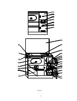
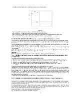
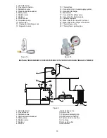
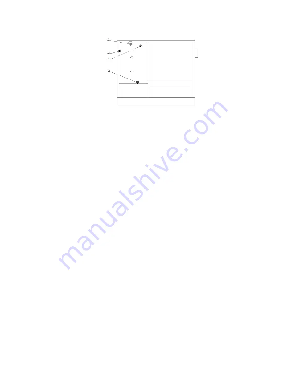
The back of the boiler and connections are shown in Fig. 4 where: 


                              Figure 4 

- Item 1 is an R1" connection with an outer thread for the flow pipe,  
- Item 2 is an R 1" connection with an outer thread for the return pipe,   
- Item 3 is an R1/2" connection with an inner thread for installation of the thermal valve safety pipe,  
- Item 4 is an R1/2" connection with an inner thread for safety valve installation.   
 

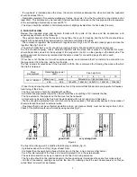
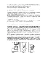
6.1 DISCHARGE AND RETURN LINE (fig.4 pos.1 and 2 and fig.7 and fig.8 pos.3 and 10) 

The  outlets  of  the  discharge  and  return  water  of  the  boiler  are  1"  and  they  must  not  be  reduced,  that  is, 
narrowed up to the first bifurcations. Use steel pipe 1" or copper pipe with external diameter F28mm. (or bigger 
diameter). 
When  performing  the  installation,  strictly  pay  attention  to  the  pipe  slopes  which  should  be  0,5%  (5mm.  per 
meter of pipe) and to the system venting (boiler, pipes, radiators). 
On the discharge line you may set thermal-manometer although thermometer and manometer are mounted on 
the front side.  
Set a “by-pass” on the return line with a pump, expansion vessel and valve for filling and draining the system. 
When mounting the pump, pay attention to the pump direction.  

Warning: 
Make a "by-pass" only if there are conditions for so called gravitational heating. 

.  6.2   THERMAL VALVE WITH BUILT-IN THERMAL PROTECTION AND ADDITIONAL ELEMENTS FOR 
CONNECTION 

To install thermal valve it is necessary to purchase and install: 
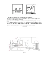
1. Thermal valve with built-in thermal protection type 544, 1/2", product Caleffi (Fig. 7a) and Fig. 7, Item 13. 
2. Slope pressure regulator with manometer 1/2", the same or similar as shown in Fig. 7b and Fig. 7, Item 19. 
3. Filter for cold water at the input of the water supply to the thermal valve, Fig. 7, Item 20 
4. Filter for hot - boiling water intake of the boiler and water outlet of thermal valve, Fig. 7, Item 21. 
 

Note: 

These components are not included with product for central heating you bought! 
Installation  of  thermal  valve  with  built-in  thermal  protection  (Fig.  7,  Item  13  and  Fig.  7a)  with  additional 
elements ensuring safe operation, such as pressure regulator (Fig. 7, Item 19 and Fig. 7b). Water filter on the 
boiler  intake  (Fig.  7,  item  20)  and  water  filter  on  the  boiler  outlet  in  closed  central  heating  system  is 
MANDATORY.   This specially refers to a closed system, when the radiators are submerged and where in case 
of termination of the pump operation for any reason, the water temperature in the boiler rapidly increases and 
overheating occurs very quickly.  
In the open central heating system, installation of thermal fuse is not mandatory.  
 

6.2.1  THERMAL VALVE WITH BUILT-IN THERMAL PROTECTION (Fig. 7, Item 13 and Fig. 7a) 

 
Thermal fuse is installed near the stove, depending on the available space. It can be installed in any position. 
You  should  take  into  account  the  direction  of  cold  water  intake  and  hot  water  outlet  from  the  boiler  which  is 
clearly marked on the valve body.   
The thermal fuse probe (Fig. 7, Item 22) is best to place in the thermal valve connection (Fig. 7, Item 18). It can 
be placed on the discharge - distribution pipe (Fig. 7, Item 3) but at a distance from the boiler of 500 mm the 
most or at the highest point of the boiler before the exhaust pipes. 
Seal it with hemp or other sealing material by tightening.  
Fig. 7 shows the thermal valve installation diagram. 

Summary of Contents for 20

Page 1: ...1 STOVE FOR FLOOR HEATING ALFA TERM 20 INSTRUCTIONS FOR INSTALLATION ADJUSTMENT AND USE ...

Page 2: ... mm Height min max 264 452 mm Depth 414 mm OPENING OF FIREBOX DOOR width height 175 200 mm CONNECTIONS OF DISCHARGE AND RETURN LINE R1 RS CONNECTIONS OF THERMO VALVE AND SAFETY VALVE R1 2 RU CONNECTIONS OF COOLING PIPES R1 2 RS BOILER VOLUME 14 l HEATING VOLUME WITH GRATE IN LOWER POSITION 280 380m3 total Heating volume of stove emission 100 135 m3 Heating volume of hot water radiators 180 230 m3 ...

Page 3: ... The stove for floor heating is constructed so that it enables maximum safety during operation Safety during stove operation is provided in three ways combustion regulator thermostat fig 1 pos 10 located in the ashtray door which automatically closes the air intake in the stove firebox when the set water temperature in the boiler is reached Thermal valve thermal fuse Fig 7 Item 13 and Fig 7a when ...

Page 4: ...4 1 2 18 7 16 17 13 11 25 12 3 4 5 6 15 14 19 20 21 22 7 8 16 17 10 11 9 23 24 9 Figure 1 ...

Page 5: ...aches its rated power if the flue draft is 20Pa We recommend the following flue sizes with which this draft is obtained Stove Denotement Rated heating power kW Flue height m 6 7 8 9 10 ALFA TERM 20 Brown coal wood Dimensions of light surface mm 22 8 22 9 145x200 145x145 145x145 145x145 145x145 Proper flue and meeting other requirements set out in the material that follows are a prerequisite for fl...

Page 6: ...erformed by a qualified person according to the appropriate project The stove is intended for floor and central heating It can be installed in closed and open heating system Adhere to the regulations JUS M E7 201 and JUS M E7 202 Diagrams of closed and open system are shown on fig 7 and fig 8 ...

Page 7: ...ator with manometer 1 2 the same or similar as shown in Fig 7b and Fig 7 Item 19 3 Filter for cold water at the input of the water supply to the thermal valve Fig 7 Item 20 4 Filter for hot boiling water intake of the boiler and water outlet of thermal valve Fig 7 Item 21 Note These components are not included with product for central heating you bought Installation of thermal valve with built in ...

Page 8: ...4 WATER FILTER OF THE BOILER OUTLET Fig 7 Item 21 It is required to install the filter on the boiler outlet which will clean the hot boiling water from dirt and solid objects that can damage the tap seals or seals of the thermal valve This filter must be resistant to water temperatures up to 150 C NOTES After the completion of thermal valve activation checking the pressure in the installation and ...

Page 9: ...th pressure of 2 4 bar It is desirable that water is drained out from the system at least once because of the grime located in the system For an installation in which only a stove alfa term 20 is connected we recommend expansion vessel from 18 l but not less than 12 l which would be placed on returning water as close as possible to the boiler and no block valve should be set between the boiler and...

Page 10: ...ressure regulator 20 Water filter at the input of the boiler 21 Water filter at the output of the boiler 22 Thermal fuse probe 23 Thermal fuse capillary pipe Figure 7a Figure 7b INSTALLATION DIAGRAM OF OPEN SYSTEM OF STOVE FOR FLOOR HEATING ALFA TERM 20 10 9 6 8 1 3 16 7 11 2 12 5 15 4 14 13 Figure 8 1 Hot water boiler 2 Flue extension 3 Distribution line 4 Open expansional vessel 5 Safety valve 6...

Page 11: ...on which consumers radiators are connected with a minimum power of 8 kW When the system is cold the flap of the power regulator combustion regulator thermostat located in the ashtray door fig 1 pos 10 and pos 19 should be open Pull ahead the butterfly knob for opening and closing fig 1 pos 4 and fig 16 That way the butterfly knob is open and kindling is enabled Later when the stove is inflamed we ...

Page 12: ...enters first and then put down the front part of the grate Move the grate forward and backward so that it lies well in the grate carrier bearing Put the hob in the carrier bearing of the hob frame Placement of the grate in lower position fig 9 and 10 is performed in the same manner as the upper position provided that in the end the front part of the grate is lifted a little and through the rectang...

Page 13: ...irewood 15300 WARNING In order to get rated heating power and as higher rate of usage we recommend that you use dry beech wood cut with a length of L 33cm as a heating material 14 CLEANING AND MAINTENACE Before every filling with fuel the stove grate must be cleaned with a spade by opening the ember holders or through the open door of the firebox The ash from the ashtray should be removed at least...

Page 14: ...rain water from the installation Safety valve failure Replace safety valve 6 Sudden water temperate increase in the installation Air in the installation Perform radiator venting Closed valves towards radiators Open all valves in the heating system and provide normal water circulation in the installation Circulation pump failure The circulation pump should be repaired or replace it thereby allowing...

Page 15: ...Select low speed Air in installation Release air from the heating system Loose knobs or some screw on the stove Tighten knobs and screws 11 Sounds in the pump The pressure at the pump suction part is to low Increase system pressure or check the expansion vessel 12 The stove overheats loud noise cracking is heard in the boiler of the stove Electricity outage has occurred the circulation pump does n...

Page 16: ...gh a thermostat or shortly open the ashtray door 18 There is too much heat in baking cooking The thermostat is set to a high temperature Reduce water temperature through the thermostat or stoke moderately 19 The boiler stove releases smoke during initial startup Combustion and heating of the stove and flue It is normal for the stove to release some smoke during initial startup and this stops after...

Page 17: ...he guaranteed period with original spare parts for which we also provide a guarantee under the same conditions This guarantee does not exclude or affect the rights of the customer in regard to the conformity of the goods pursuant to the legal regulations If the delivered product does not conform to the agreement the customer has the right to ask the seller to repair that lack of conformity without...

Page 18: ...18 Overall dimensions of stove ALFA TERM 20 300 309 712 781 797 806 64 152 268 5 64 235 1 1 1 2 RU 1 2 RU 1 2 RS 1 2 RS 880 850 100 500 1448 900 Ø146 Ø142 690 132 65 600 197 24 5 35 35 107 ...

Reviews: