background image


12 

on the regulation knob. The cooker power 

is regulated by turning the knob ‘’+’’ to increase and the knob ‘’-‘’ to 

reduce the power. 
In the power regulation system, air regulator (damper) fully controls combustion air supply if other openings are 
closed. 


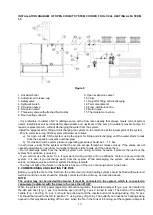
 Figure 13  


11.


SECONDARY AND TERTIARY AIR REGULATORS 


Secondary air regulator is placed in the firebox door (Fig. 15). It controls additional lighting of fire and burning of 
unburned flue gases. The secondary air is adjusted using the lever on the internal side of the firebox door. On 
the internal side of the firebox door, there is a clear marking 0-1. If the lever is moved in 0 direction, the quantity 
of the secondary air is decreased, while it is increased if the lever is moved in 1 direction. 
Leave the secondary air regulator open when the fire in the cooker is lit. 
Behind the rosette cover, there is a tertiary air regulator (Fig. 1, pos. 17). It controls additional lighting of fire and 
burning  of  unburned  flue  gases.  The  opening  and  closing  of  the  rosette  cover  is  done  using  the  lever  located 
between the lower part of the rosette cover (Fig. 1, pos. 16) and opening cover (Fig. 1, pos. 14). 

. The signs ‘’+’’ 

and  ‘’–‘’  are  written  on  the  lever.  By  turning  the  lever  ‘’+’’  you  increase  tertiary  air,by  turning  it  at  ‘’-‘’  you  can 
reduce the air. 
Leave the tertiary air regulator open when the fire in the stove is lit. 


12. COOKING, BAKING, AND FRYING 

During heating season, the cooker is used mainly for heating. For faster baking, cooking and frying, use only dry 
firewood. 
While baking, the butterfly (Fig. 1, pos. 4) for fire starting has to be closed, the rosette button for heating-baking 
has  to  be  in  position 

“1”  (Fig.  13,  pos.  19),  power  regulator  has  to  be  open  and  the  stove  covers  have  to  be 

raised  using  the  key  (Fig.  18).  After  you  finish  baking,  cooking  or  frying,  place  the  power  regulator  in  desired 
position and the rosette button for heating-baking to position 

“0”. 

While baking, increase the temperature of the water in the system to at least 60

C and, if necessary, close some 

of the radiators during baking and adjust the oven temperature to the food being prepared. 


13. FUEL 

Fuel can be stored in the fuel box (Fig. 17). The fuel box is moved on guides. If you want to take the fuel box out 
of the cooker, you must lift it to remove it from the guides. 
Use the fuel specified in Table 1 to ensure the nominal heating capacity of the boiler at chimney draft of 25 mbar 
(25 Pa).  
Do not burn coal dust, sawdust, or waste that generates large quantities of smoke!  

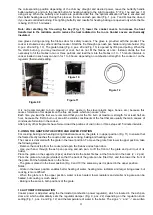
Figure 15 

Figure 15 

Summary of Contents for Alfa Term 35

Page 1: ...1 LOCAL HEATING COOKER ALFA TERM 35 INSTRUCTION FOR INSTALLATION SETTING AND USE...

Page 2: ...brown coal briquette 8 85 kW 8 85 kW Heating power transferred to water wood brown coal briquette 12 75 kW 12 75 kW REQUIRED CHIMNEY DRAFT 25 Pa FLUE PIPE CONNECTION DIAMETER 160 mm HEIGHT FROM THE F...

Page 3: ...ometer 4 Butterfly handle 13 Flue pipe connection 5 Oven door 14 Opening cover 6 Oven thermometer 15 Handle 7 Firebox door 16 Rosette cover 8 Ash pan door 17 Tertiary air regulator 9 Thermostat button...

Page 4: ...door 4 INSTALLING THE COOKER The stove can be installed in the kitchen or at any other appropriate place The substrate under the cooker should be non combustible In the event of a combustible substra...

Page 5: ...pipe Chimney connection should be vertically positioned Horizontal pieces of flue pipes over 0 5 m long should slope upwards by 10 toward the chimney Flue pipe connection flue pipes and chimney may no...

Page 6: ...201 and JUS M E7 202 Closed and open circuit diagrams are shown on Fig 7 and Fig 8 The back of the boiler and connections are shown in Fig 5 where Position 1 is an G5 4 connection with an inner threa...

Page 7: ...re in the boiler rapidly increases and overheating occurs very quickly In the open central heating system the installation of thermal fuse is not mandatory 6 2 THERMAL RELEASE VALVE WITH INSTALLED THE...

Page 8: ...be set at 2 5 to 3 bars You can fit it directly on the connection or at a distance from the connection of at least 1 m provided that there is no block valve between the boiler and the safety valve In...

Page 9: ...ump 8 Non return valve 9 Expansion vessel 10 Three way valve with attached thermostat 11 Floor heating collector 12 Cold water filter 13 Slope pressure regulator with pressure gauge 14 Hot water filte...

Page 10: ...r starts to leak and then close them Do not discharge water from the heating system even during summer because it protects the inside of the system from oxidation corrosion If you will not use the boi...

Page 11: ...rength for at least half an hour because the first to burn out are all the volatile constituents of the fuel that are usually the main causes of condensate formation in the cooker After plenty of hot...

Page 12: ...and are written on the lever By turning the lever you increase tertiary air by turning it at you can reduce the air Leave the tertiary air regulator open when the fire in the stove is lit 12 COOKING...

Page 13: ...hotplate occasionally using fine sandpaper and in the event of longer breaks apply acid free oil on the hotplate vegetable oil Remove burnt material from the cooktop with a spatula knife or treat it w...

Page 14: ...r in the installations Release air from the system 8 Circulation pump does not activate or it trips the switch No power at electrical connection Connectors are loose Check and tighten all screws at co...

Page 15: ...rs Not enough fuel has been loaded in the firebox Increase the quantity of fuel in the firebox 16 Fire is not burning regularly Low chimney draft Build a new chimney or repair the old one Connecting f...

Page 16: ...result of too high or too high voltage as well as of force majeure Defects on the device may be removed even after the expiration of the warranty using the original replacement parts for which we also...

Page 17: ...17 OUTLINE DIMENSIONS OF ALFA TERM 35 COOKER Figure 19...

Reviews: