alfasolar GmbH
Ahrensburger Str. 4 6, 30659 Hannover
Geschäftsführer:
Dipl.-Ing. M. Denz (CEO) / Dipl.-Kfm. K.-W. Hoffmann (CFO)
Amtsgericht Hannover HRB 544 55
Gerichtsstand und Sitz: Hannover
Seite 17 von 29
Tel:
Fax:
Mail:
Web:
+49 (0) 511-261 447-0
+49 (0) 511-261 447-50
sales@alfasolar.de
www.alfasolar.de
Revision-Index:
Issued:
Doc.-Nr.
08
2012-12-13
ALE-IEC-01
Preparation for the installation of the module rows
Prepare the cabling including feed and return lines up to the module rows. For modules with
connector plugs, route cables with connector plugs (e.g., MC4-adapter set with heat-shrink
sleeve and crimping connectors for crimping) lead to the individual end modules of the strings.
It is necessary to first plan how the modules can be wired over multiple rows (this allows the
location of the outlets and the + and terminals of the individual modules to be) and order any
necessary additional materials.
When laying the module string cables, make sure that the + line and the line of the string are
laid together tightly to prevent electrical surges through the surface of the string conductor loop
in the event of a nearby lightning strike
.
The return line should take the same path as the passage of the current through the module so
that the feed and return line can be routed off the roof to the same site. The return line can
now be fastened in the lateral cable channel of the mounting.
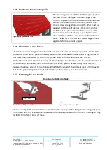
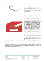
Together with our rail we deliver a PV-clamp
(see figure 10). The fixing of the clamp is to be
done by clicking it into the profile of the rail
so it can be moved and removed at any time.
We recommend the application of one clamp
per meter.
Pay particular attention to the polarity of the solar modules. Reversing the polarity will de-
stroy the bypass diodes.
Our modules are mainly sold with junction box type PV 1410-2 (4 or 6 poles) which contain
diodes type Diotec SB 1240. The diodes have the following electrical characteristics:
Max. peak reverse voltage: 40V
Forward rectified current: 12A
Max. Junction temperature: 200°C
Replacement diodes can be ordered at alfasolar GmbH.
If you have bought a monocrystalline module with ISBT junction box the overcurrent protec-
tion is provided by an electronic chip, Type Microsemi with the following ratings:
Max. peak reverse voltage 24V
Forward Rectified current 25 A
Max junction temperature 225°C
The junction box with cables connected at the factory does not have to be opened for the
electric wiring of the solar modules.
Lay cables with strain relief, lay them mechanically stress-free and with sufficient large bend-
ing radii. If necessary, secure lines using cable ties.
The cross section of the connecting cable must not be smaller than 4 mm².
Fig. 10: Fixing the cable at A2 mounting rail with PV-clamp


