alfasolar GmbH
Ahrensburger Str. 4 6, 30659 Hannover
Geschäftsführer:
Dipl.-Ing. M. Denz (CEO) / Dipl.-Kfm. K.-W. Hoffmann (CFO)
Amtsgericht Hannover HRB 544 55
Gerichtsstand und Sitz: Hannover
Seite 20 von 29
Tel:
Fax:
Mail:
Web:
+49 (0) 511-261 447-0
+49 (0) 511-261 447-50
sales@alfasolar.de
www.alfasolar.de
Revision-Index:
Issued:
Doc.-Nr.
08
2012-12-13
ALE-IEC-01
3.4.11
Installing module rows
G
E NE R AL IN D IC AT IO NS
:
The modules are normally installed with their long sides orientated vertically. Besides that the
modules can also be installed with their long sides horizontally.
Regarding the permissible loads you have to attend to the fixing specifications indicated below.
Solar modules have to bear on the mounting system with at least four points on two opposite
sides.
The fixing of the module can be done using the boreholes (tolerances: ± 90 mm,
see Chapter 3.5
F
or integration systems.
Optimal adjustment and inclination
For maximum power you should determine the optimal adjustment and orientation of your
solar modules. The highest solar power is created when sunlight shines in an angle of 90°.
CAUTION: Avoid shading!
Power losses can be indicated by half shadowing (e.g. caused by dirt). Take care that dirt does
not remain on your module for longer time. Alfasolar modules have been tested against hotspot
but still - if dirt remains too long a hotspot could occur damaging single cells, double strings or
the whole module.
A solar panel is called "shadow-free", when the entire surface is freely accessible over the whole
year. A shadow-free module is reached by solar radiation even on the shortest day of the year.
Ventilation
To avoid high temperatures the stand-off between your solar modules and the mounting
ground is min. 5 mm. Additionally you can avoid high moisture by keeping a sufficient stand-off.
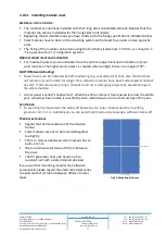
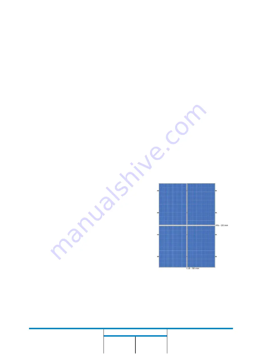
Thermal extensions
Regard the thermal extension of the module
frames
Solar modules are not to be mounted together
too tightly.
The min. distance between solar modules has to
be 8 10 mm.
We recommend a distance of 20 mm between
the rows.
The PV generator has to be fixed on a fire-
resistant roof with a determined static load.
If you use other mounting material than alfasolar
components please regard the electrochemical series
to avoid contact corrosion between different metal
types.
Fig.13: Mounting distances

