background image


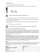
Working with core drills 


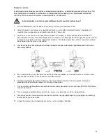
  Push the ejector pin (centering pin) through the core drill head. 


  Core drills with Weldon shank are tightened with clamping screws (DIN 913) on both clamping surfaces. 


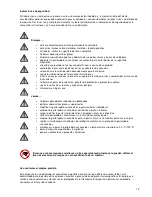
Risk of injury! Always wear gloves since the edges are sharp. 


  Set the core drill on the work piece and start drilling until the whole cutting area is marked as a circular ring. 


  The core drill should be cooled constantly during the drilling process. Optimum cooling is possible through our  


coolant equipment using internal cooling. 


  Do not switch the drive motor off during drilling, and after the drilling process pull the core drill back with the 


motor still running. 


  Remove swarf and core after every drilling process. 


Use a swarf key to remove the swarf. Do not touch with your bare hands. Risk of injury! 

 
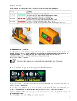
Special information on handling switchable permanent magnets 
 

The magnetic surface is located on the underside of the core drilling machine and generates the magnetic holding 
force when the magnet is activated. The magnet can be activated independently of the 110 volt supply by pressing 
the lever down. For the magnet to be released the black safety tab must be pushed in using the ball of your hand 
and the lever pulled upwards. The machine remains attached to the work piece even in the event of a power failure 
when the lever is still in the down (activated) position 


Material thickness 

The magnetic flow of the TML permanent magnet requires a minimum material thickness of approx. 3/8” (8 mm) to 
be completely absorbed by the work piece. If this material thickness is not sufficient, the maximum holding force is 
reduced in accordance with the material thickness. Conventional electric or permanent magnets have a deeply 
penetrating magnetic field similar to deep tree roots, and require a large material thickness of more than 1” (25 mm) 
to achieve the maximum holding force. The compact magnetic field of the TML magnets is similar to a shallow root 
and achieves maximum holding force even with small material thicknesses, so that drilling can be done with 
sufficient holding force even on thin sheets from only 1/8-5/32” (3–4 mm) thick. 

 
Material 

The load-bearing capacity of the permanent magnets is determined using AISI1020 steel. Steels with a high carbon 
content or whose structure has been changed by heat treatment have a low holding force. Foamed or pore-flawed 
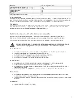
cast parts also have a lower holding force.  This chart shows a comparison of the expected holding force on 
different materials. 


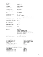
Material 

Magnetic force in % 

Non-alloyed steel (0.1-0.3% C content) 

100 

Non-alloyed steel (0.3-0.5% C content) 

90-95 

Cast steel 

90 

Grey cast iron 

45 

Nickel 

11 

Stainless steel, aluminium, brass 


Summary of Contents for ROTABEST RB 50 SP

Page 1: ...Operation Instructions Manual de instrucciones ALFRA ROTABEST RB 50 SP Metal Core Drilling Machine Taladro electromagnético Prod No 18850 110 UL Nº de producto 18850 110 UL ...

Page 2: ...re parts Please read and save these instructions Page 3 Indicaciones de seguridad uso conforme al empleo previsto datos técnicos accesorios disponibles descripción del dispositivo puesta en servicio LED sensor magnético parada de emergencia del motor desactivar el sensor y la parada de emergencia automática del motor LED motor en el panel de mando control de desgaste de los carbones trabajar con p...

Page 3: ...nd ear protection during work observe local and country specific guidelines store in a dry place Never work on round or curved objects use a pipe adapter if this is necessary drill several work pieces on top of one another modify the core drilling machine or remove signs use the core drilling machine when damaged or when parts are missing strain or damage the underside of the magnet through heavy ...

Page 4: ...BS 11 5 kg Further functions Smooth start Motor emergency stop Motor temperature control Carbon brush wear control Quick change tool holder for core drill Magnetic field sensor Noise emission 92 dB A 300 mm distance from the motor Vibration on the handle AC 3 5 mm s and VC 3 2 mm s Available accessories Prod No Tool holder AMK 2 MK 2 Tool holder AMK 2 MK 2 Carrying case 18001 without internal cool...

Page 5: ...cate the operating state of the motor and the magnet s holding force A self adjusting dovetail guide which the motor is attached to can be vertically adjusted using the star handle The type plate and an attachment location for the Allen keys included can be found on the back of the machine A Drive motor G Safety tab 1 Motor ON B MT2 arbor H Operating panel 2 LED for motor control C Slide and setti...

Page 6: ... of the machine on vertical walls or for overhead work Secure the drilling unit using the safety belt when working on walls and ceilings 4 Press the lever down as far as it will go and make sure that the safety tab audibly latches into place 5 As soon as the sensor LED lights up green or flashes red you can activate the motor by pressing the MOTOR ON key on the operating panel at the side 6 Turn t...

Page 7: ...air gap under the magnet As soon as the magnet is no longer touching the surface the motor is automatically deactivated and the magnet LED lights up red constantly However the motor is not braked It is only possible to restart the machine after having switched the magnet on and off Deactivating the sensor and the automatic motor emergency off Depending on your core drilling machine model it is pos...

Page 8: ...D green Carbon brushes are worn and must be replaced Carbon brush wear control The core drilling machine has an integrated carbon brush wear control feature so that the motor LED flashes as soon as the carbon brushes have been worn down to a certain level by mechanical abrasion Replace the carbon brushes as soon as possible and always both at the same time In order to replace the carbon brushes re...

Page 9: ...e remains attached to the work piece even in the event of a power failure when the lever is still in the down activated position Material thickness The magnetic flow of the TML permanent magnet requires a minimum material thickness of approx 3 8 8 mm to be completely absorbed by the work piece If this material thickness is not sufficient the maximum holding force is reduced in accordance with the ...

Page 10: ...perations otherwise there is a risk of injury due to unintentional machine switch on Before every use inspect the core drilling machine and underside of the magnet for visible signs of damage clean the surface of the work piece and the underside of the magnet check the blocking function of the safety tab on the lever check the correct firm fit of the core drill check connection cables for damage W...

Page 11: ...RA Rotabest RB 50SP complies with the following directives Machinery Directive 2006 42 EC Low Voltage Directive 2006 95 EC Electromagnetic Compatibility EMC 2004 108 EC The following standards or normative documents were applied EMC Directive EN 55014 1 2006 EN 55014 2 1997 A1 2001 EN 61000 3 2 2006 EN 61003 3 3 1995 A1 2001 A2 2005 Document officer Cornelia Dorn Hockenheim 9 10 2014 ...

Page 12: ...protección guantes de protección y protección auditiva seguir las directrices locales y específicas del país almacenar en lugar seco Jamás trabajar sobre objetos redondos o abombados perforar sobre varias piezas superpuestas modificar la perforadora sacanúcleos o quitar carteles indicadores emplear la perforadora sacanúcleos con daños o piezas faltantes cargar o dañar la parte inferior del imán co...

Page 13: ...ntrol de temperatura del motor Control de desgaste de escobillas de carbono Alojamiento de cambio rápido para brocas sacanúcleos Sensor de campo magnético Emisión de ruidos 92 dB A 300 mm distancia del motor Vibración en la empuñadura AC 3 5 mm s y VC 3 2 mm s Accesorios disponibles Portaherramientas AMK 2 MK 2 Portaherramientas AMK 2 MK 2 Art n 18001 sin refrigeración interno 18003 con refrigerac...

Page 14: ...ia de los imanes Una guía de cola de milano autoajustable en la que está fijado el motor se puede regular en altura a través del torniquete En el lado posterior de la máquina se encuentra la placa de características y una posibilidad de fijación para las llaves de hexágono interior adjuntas A Motor de accionamiento G Pletina de seguridad 1 Motor ON B CM 2 H Panel de mando 2 LED para control del mo...

Page 15: ... la máquina en paredes verticales o posiciones forzadas Al trabajar en paredes y techos asegurar la unidad de perforado con la correa se seguridad 4 Presione la palanca hacia abajo hasta el tope y observe de que la pletina de seguridad encastre de forma claramente audible 5 En el momento de que el LED del sensor brille en verde o parpadee en rojo puede activar el motor a través del panel de mando ...

Page 16: ...recarga vibración u otras causas se genera una hendidura de aire debajo del imán En el momento que el imán se suelta se desactiva automáticamente el motor y el LED del imán brilla constantemente en rojo El motor sin embargo no se frena Un reinicio de la máquina recién es posible tras desconectar y conectar el imán Desactivación del sensor y la parada de emergencia automática del motor Según la eje...

Page 17: ...billas de carbono están desgastadas y deben ser sustituidas Control de desgaste de los carbones La perforadora sacanúcleos dispone de un control integrado de desgaste de los carbones de manera tal que el LED Motor brilla en rojo en el momento que las escobillas de carbono se han consumido adecuadamente debido a la abrasión mecánica Sustituya las escobillas de carbono lo antes posible y siempre amb...

Page 18: ...e activarse independientemente de la tensión de la red presionando hacia abajo la palanca Para soltarlo se debe presionar la pletina de seguridad negra hacia dentro con el pulpejo y la palanca ser tirada hacia arriba También en caso de interrupción de corriente la máquina permanece adherida a la pieza Grosor del material El flujo magnético de los imanes permanentes TML necesita de un grosor de mat...

Page 19: ...ento se asignan de acuerdo a la frecuencia de ejecución recomendada Antes de realizar trabajos de conservación extraer siempre primero la clavija de red en caso contrario amenaza peligro de lesiones por una conexión involuntaria de la máquina Antes de cada uso comprobar visualmente la presencia de daños en la perforadora sacanúcleos y la base magnética limpiar la superficie de la pieza y la superf...

Page 20: ...reparar solo puede ser realizado por profesionales electricistas de acuerdo a las normas vigentes en el país correspondiente Emplear únicamente repuestos ALFRA Sinopsis de repuestos al final de estas instrucciones de servicio ...

Page 21: ...LFRA Rotabest RB 50SP cumple las siguientes directivas Directiva de máquinas 2006 42 EG Directiva de baja tensión 2006 95 EG Compatibilidad electromagnética CEM 2004 108 EG Se han aplicado las siguientes normas o documentos normativos Directiva CEM EN 55014 1 2006 EN 55014 2 1997 A1 2001 EN 61000 3 2 2006 EN 61003 3 3 1995 A1 2001 A2 2005 Apoderada de documentación Cornelia Dorn Hockenheim 9 10 20...

Page 22: ...22 Spare Parts ...

Page 23: ... mains cord with plug 31 1 189414094 keypad ON OFF 32 1 189414047 bar magnet 33 2 W1451 3x8 A2 lens head screw 34 1 03191 021 pressure spring 35 1 189414087 lug lever 36 1 DIN7 10X45 m6 A2 dowel pin 37 1 189412068 insertion lens 38 1 189414075 side cover left 39 13 ISO7380 M3X8 10 9 round head screw 40 4 DIN912 M5X12 8 8 A2R cylinder screw 41 1 189414090 magnet holder 42 7 ISO7380 M4X8 10 9 A2R ro...

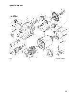
Page 24: ...24 Exploded drawing motor ...

Page 25: ...haft with 2 gears 19 1 189502091 sealing sleeve 20 1 189502087 rotary shaft seal 21 1 189502021 deep groove ball bearing 23 1 189502078 work spindle 31 1 189411085 deep groove ball bearing 32 1 189502032 spindle gear 33 1 189502033 feather key 34 1 189502034 adjusting washer 35 1 189502035 retaining ring 36 1 189502036 shaft for cluster gear 37 1 189411086 deep groove ball bearing 38 1 189502095 c...

Page 26: ...26 ...

Page 27: ...27 ...

Page 28: ...28 Alfred Raith GmbH 2 Industriestr 10 D 68766 Hockenheim Tel 06205 3051 0 Fax 06205 3051 150 Internet www alfra de E mail info alfra de 02 2015 ...

Reviews: