background image

4 Operation and running

Eder GmbH

18 / 108

Operating Instructions Algema Blitzlader 2 Air - Edition 04/2021

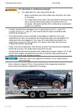
Unsecured or poorly secured load!

The load can shift, roll away or be thrown from the car carrier 

while driving.

°

Secure the load properly (

see "Securing the loaded vehicle", 

page 23

).

°

Safely stow tools and supplies.

°

Remove loose objects on the plateau.

°

Always check the adjustable wheel stop for tight fit.

°

Observe national regulations on load securing.

°

Check load securing after a distance of approx. 50 km and 

during breaks in the journey, retighten if necessary.

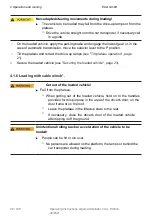
Unsuitable, defective or incorrectly used lashing equipment!

The safety belts can tear, the load can shift during the journey, roll 

away or be thrown from the car transporter.

°
°

°

Only use certified safety harnesses (TÜV,GS).

°

Use suitable safety belts (

see "Securing the loaded vehicle", 

page 23

).

Check the securing straps for damage before lashing.  Max. 
Observe lashing forces and min. lashing angle.

Eder GmbH

4 Operation and running

Operating Instructions Algema Blitzlader 2 Air - Edition 04/2021

19 / 108

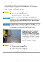
Work with the winch*!

Danger of crushing on the rotating drum of the cable winch or on 

the cable hook.
The rope may break.
Persons can be injured by the tensioning rope when pulling the 

winch.
People can trip over the taut rope.

°
°

°

°
°

Do not use damaged ropes.
Do not reach into the drum of the cable winch when the

freewheel is deactivated.

°

No persons may be behind the vehicle to be loaded or unloaded

as long as the vehicle is held by the rope.
No persons are allowed on the plateau, in the area of the drive-

up ramps and generally between the winch and the vehicle to 

be transported when a load is applied to the rope.
Wear work gloves when working with the rope.
When pulling, always make sure that the rope is wound neatly 

onto the drum.

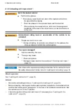
Defective hydraulic parts!

Risk of injury from a hydraulic fluid escaping at high pressure.
Hydraulically moving parts can yield unexpectedly in the event of 

leakage.

°

°

Never reach for lines and screw connections that are leaking.

In the event of leakage, secure hydraulically moving parts 

against unforeseen movement before reaching into the danger 

zone.

Have defective hydraulic parts replaced immediately by a specialist 

workshop.

Cargo drags across the plateau!

Damage to the car transporter.

°

Only load vehicles that can roll or use shunting rollers.

°

Remove or secure hanging components before loading.

Summary of Contents for BLITZLADER 2

Page 1: ...Operating instructions BLITZLADER 2 WITH AIR SUSPENSION ALGEMA FIT ZEL Brands of EDER GmbH ...

Page 2: ...le data Eder GmbH 2 108 Operating Instructions Algema Blitzlader 2 Air Edition 04 2021 Your vehicle data Vehicle type Chassis number Body number Gross vehicle weight rating Initial registration Special equipment ...

Page 3: ...afe and comfortable on the road We want you to be able to use your new vehicle effectively for a long time That s why we focus on high quality and durability in the technical systems materials and workmanship Like any technical device your Blitzlader 2 with air suspension and its superstructure require a minimum of care and maintenance We will support you in this Please have the required function ...

Page 4: ...ipment 8 1 4 Supplementary documents 8 1 5 Liability and warranty 9 1 6 Changes 9 1 7 Storage note 9 1 8 Copyright 9 2 Safety 10 2 1 General safety instructions 10 2 2 Personnel requirements 10 2 3 Explanation of the safety instructions in these operating instructions 11 3 Description 12 3 1 Overview 12 3 2 General description 13 3 3 Intended use 14 3 4 Foreseeable misuse 14 ...

Page 5: ...ball on the loading area 35 4 2 Checking before starting the journey 37 4 3 Attaching the trailer coupling 38 4 4 Radio remote control 42 4 5 Lighting 46 4 5 1 Lighting according to StVZO 46 4 5 2 Rotating beacon worklights and ambient lighting front and rear 46 4 6 Toolbox 49 4 7 Center ramp 50 4 8 Lift axis 51 4 9 Emergency operation 54 4 9 1 Emergency operation electrohydraulics 54 4 9 2 Emerge...

Page 6: ...ls 69 5 4 2 Air suspension 70 5 4 3 Testing steel ropes 72 5 4 4 Checking the plastic rope 73 5 4 5 Changing illuminant 74 5 4 6 Checking the oil level and changing the oil 77 5 4 7 Lubricating and greasing moving parts 79 5 5 Cleaning 82 5 6 Power unit and fuse 83 5 6 1 Power unit 83 5 6 2 Fuses 84 6 Disposal 87 7 Additional information 88 7 1 Warranty conditions warranty processing 88 7 2 Compla...

Page 7: ...f the base vehicle Scope of equipment These operating instructions and any supplementary instructions describe the scope of equipment intended at the time of printing We reserve the right to make changes in the interest of technical progress and improvement Illustrations are for information only and may differ from the original Attention We expressly point out that we accept no liability whatsoeve...

Page 8: ...pecific vehicle license is sometimes required for driving a car transporter StVO Find out about the country specific requirements 3 Special equipment Equipment marked with a star symbol is part of the optional equipment 4 Supplementary documents The EU directives valid at the time of production apply to the car transporter In addition the following must be observed The operating instructions of th...

Page 9: ...y processing page 88 6 Changes Changes in these operating instructions can be made without further notice The latest version can be obtained from the manufacturer Updated operating instructions are not subsequently supplied www algema fitzel de 7 Storage advice These operating instructions are an integral part of the product and must be available in full at all times A missing operating manual or ...

Page 10: ...s on the plateau must be removed see Loading and unloading page 16 During the journey it must be possible to observe the road behind at all times through two exterior mirrors Driving the car transporter is only permitted with a valid and appropriate driver s license Familiarize yourself with the driving and braking behavior of the car transporter in difficult road and weather conditions e g downhi...

Page 11: ...njury will occur if the corresponding precautionary measures are not observed Places marked with this symbol indicate that death or serious injury may occur if the corresponding precautionary measures are not observed Places marked with this sign indicate that slight physical injury may occur if the corresponding precautionary measures are not observed The text of a safety notice is divided into S...

Page 12: ... driver s cab Warning console Filling valve Air spring Flyer Adjustable front wheel stop Adjustable rear wheel stop Manual control panel for plateau ramps and winch Operation of lift axis Electric winch Aluminum perforated railing Plateau Loading ball on loading platform air spring Spare wheel 2 pieces if necessary Center ramp retracted Drive up ramps Trailer hitch not shown Optional equipment ...

Page 13: ...uble cab Ford Transit with rear wheel drive and single cab Opel Movano Renault Master with front wheel drive and single cab The frame with rear axle is expertly separated from the base vehicle behind the driver s cab so that only the power car remains The plug in units with a pivot point for the plateau are flanged to this The plateau consists of a sturdy steel frame and a transversely planked alu...

Page 14: ...ust be observed and all safety relevant values must be complied with in accordance with the respective technical data Any other use beyond this is considered improper EDER is not liable for any damage resulting from this Intended use also includes compliance with the maintenance obligation see Care and maintenance page 65 4 Foreseeable misapplication EDER is not liable for personal injury or prope...

Page 15: ... of safety relevant components by laypersons Removing or obscuring the nameplate Leaving renting the car transporter without handing over the operating manual and instruction in its operation Use of the winch for purposes other than loading and unloading the vehicle to be transported Operating Instructions Algema Blitzlader 2 Air Edition 04 2021 15 108 ...

Page 16: ...the warning console switched on and the warning triangle If necessary enlist the help of another person to secure the area Wear high visibility vests Loading and unloading on slopes and uneven ground The car transporter may start moving uncontrollably or tip over The car transporter can be damaged e g frame damage Firmly apply the parking brake If possible load and unload the car transporter on fi...

Page 17: ...hoes Do not stand behind the drive up ramps Tilting plateau during loading and unloading Crushing of body parts on the moving parts of the transporter Risk of injury due to slipping load and tilting platform Observe tilting movement of the plateau Make sure that no body parts are located between or under the moving parts No other persons may be in the area of the moving parts Slippery plateau due ...

Page 18: ...ustable wheel stop for tight fit Observe national regulations on load securing Check load securing after a distance of approx 50 km and during breaks in the journey retighten if necessary Unsuitable defective or incorrectly used lashing equipment The safety belts can tear the load can shift during the journey roll away or be thrown from the car transporter Only use certified safety harnesses TÜV G...

Page 19: ...nd generally between the winch and the vehicle to be transported when a load is applied to the rope Wear work gloves when working with the rope When pulling always make sure that the rope is wound neatly onto the drum Defective hydraulic parts Risk of injury from a hydraulic fluid escaping at high pressure Hydraulically moving parts can yield unexpectedly in the event of leakage Never reach for li...

Page 20: ...oading process 4 1 2 Loading and unloading point Load and unload away from moving traffic whenever possible Secure the loading point against moving traffic with hazard warning lights activated rotating beacon and warning triangle If necessary enlist the help of another person to provide security Wear a high visibility vest Place the car transporter on as level and firm a surface as possible Secure...

Page 21: ...p 8 Ramps from 9 Ramps on 10 Plateau on 11 Plateau from The parking brake of the car transporter must be applied and the ignition switched on so that the body functions can be activated If necessary additionally secure the car transporter with wheel chocks To avoid discharging the vehicle batteries it is recommended to leave the vehicle engine running until the charging or discharging process is c...

Page 22: ...or end position tilt scissors stops the tipping when the vehicle is on uneven ground and the tilt scissors are at the stop before the tilt sensors reach the ground The vehicle can then be loaded or unloaded and secured see 4 1 4 Securing the loaded vehicle to 4 1 9 Trailer transport with loading ball on the loading area For loading or unloading with the rope winch the rope can be unrolled with the...

Page 23: ... for a long time there is a risk of damage due to overheating The battery voltage is not monitored during operation of the electrohydraulics Due to the high current demand the vehicle batteries may be discharged when the engine is not running and the electrohydraulics are operated frequently It is recommended to keep the engine running during the charging and discharging process 4 1 4 Securing the...

Page 24: ...ed on the plateau in relation to the center longitudinal axis of the car transporter and the parking brake must be applied The lowest gear must be engaged or in the case of an automatic transmission the selector lever must be in the P position The wheels of the front axle must be in contact with the front wheel stop Fasten the second wheel stop in the same way as the front wheel stop immediately b...

Page 25: ... The loaded vehicle is positioned incorrectly Axle loads of the car transporter are exceeded The car transporter can no longer be steered safely enough due to an underloaded front axle The loaded vehicle must be positioned in such a way that the permissible axle loads of the car transporter are not exceeded To ensure steerability the front axle load of the car transporter must be more than approx ...

Page 26: ...the drive up ramps see Tilt plateau operation page 21 Secure the loaded vehicle see Securing the loaded vehicle page 23 4 1 6 Loading with cable winch Get out of the loaded vehicle Fall from the plateau When getting out of the loaded vehicle hold on to the handles provided for this purpose in the area of the driver s door on the door frame or on the roof Leave the plateau in the tilted up state to...

Page 27: ...tual weight of the loaded car transporter The rope is damaged Injuries caused by the rope The rope may break Wear work gloves Damaged ropes must not be used see Checking steel ropes page 72 Also observe the separate operating instructions for the cable winch and the safety notes under Safety notes for loading and unloading page 16 The installation situation of the cable winch may differ from the o...

Page 28: ...ol box or lo se enclosed Details on operating the winch can be found in the operating instructions for the winch Alternatively the cable winch can be operated with the radio remote control see Radio remote control page 42 Moving the winch The cable must run parallel to the direction of travel of the car transporter max 4 oblique pull if necessary you must align the cable winch as follows Release t...

Page 29: ...the freewheel pull the rope again firmly so that the freewheel clutch engages securely Do not operate the freewheel under load At least 5 rope windings must remain on the drum to be able to hold the nominal load To attach the rope hook to the vehicle to be towed observe the operating instructions for the vehicle The vehicle can now be pulled slowly onto the plateau with the winch centered on the l...

Page 30: ...orage eyelet or the loaded vehicle The battery voltage is not monitored during winch operation Due to the high current demand of the cable winch the vehicle batteries may be discharged after a short time when the engine is not running A figure of eight sling is supplied with every car transporter with winch The figure of eight sling serves as an aid if the hook of the cable winch cannot be easily ...

Page 31: ...or behind the car transporter Secure the unloading point see Loading and unloading point page 20 Before unloading check again that the parking brake is applied on the loaded vehicle and that the lowest gear is engaged or in the case of an automatic transmission that the selector lever is in the P position Loosen the safety belts Remove the rear wheel stop Extend the drive up ramps and tilt the pla...

Page 32: ...e allowed on the plateau the drive up ramps or behind the car transporter The rope is damaged Injuries caused by the rope The rope may break Wear work gloves Damaged ropes must not be used see Checking steel ropes page 72 Also observe the separate operating instructions for the cable winch and the safety notes under Safety notes for loading and unloading page 16 Winch operation See Loading with ca...

Page 33: ... the vehicle to be towed observe the operating instructions for the vehicle Tighten the cable winch until the cable is taut Loosen the safety belts Remove the rear wheel stop Extend the drive up ramps and tilt the plateau see Operating the tilt plateau page 21 The vehicle to be unloaded can now be slowly lowered from the plateau with the aid of the cable winch Observe the position of the steered w...

Page 34: ...1 After loading reactivate the winch freewheel If the winch freewheel remains deactivated unintentional operation e g radio remote control in the trouser pocket may cause damage to the winch the storage eyelet or the loaded vehicle The battery voltage is not monitored during winch operation Due to the high current demand of the cable winch the vehicle batteries may be discharged after a short time...

Page 35: ...ler socket In addition secure the trailer to its wheels on the plateau see Securing the loaded vehicle page 23 and apply the parking brake on trailers with overrun brakes Unloading is performed in reverse order see Unloading with the cable winch page 32 Only the rear lights parking lights are active on the 13 pin trailer socket Also observe the operating instructions of the trailer for the correct...

Page 36: ...r GmbH 36 108 Operating Instructions Algema Blitzlader 2 Air Edition 04 2021 The trailer must be properly lashed to the wheels The loading ball is not designed to fully absorb the horizontal forces due to braking and acceleration ...

Page 37: ...and the lowest gear engaged or in the case of automatic transmission the selector lever must be in the P position Ensure that the plateau is completely tilted down The drive up ramps and the center ramp must be completely retracted Visual inspection of the tires and chassis The body functions must be switched off switches off automatically when the parking brake is released Close and lock the tool...

Page 38: ...tain brief instructions for assembly A detailed description can be found in the enclosed operating instructions for the trailer coupling The operating instructions for the trailer coupling must be observed Mounting for ball bar at the bottom of the rear of the car transporter Trailer hitch 1 Ball bar 2 Locking bolt 3 Handwheel 4 Green area 5 Red area 6 Lock cylinder with key ...

Page 39: ...ove the key when it is unlocked If necessary unlock the locking cylinder Before mounting check that the ball bar is tensioned The locking bolt must be completely retracted in the tensioned state 2 2 If the ball bar is not tensioned pull the handwheel and turn it to the right in the pulled position 2 3 The white marking must be in the red area In the clamped state press the ball bar into the holder...

Page 40: ......

Page 41: ...l bar could be damaged and come loose during trailer operation Do not use any additional tools or aids to mount the ball bar Clean the ball bar the locking mechanism and the receptacle if the ball bar cannot be mounted by hand If it is not possible to install the ball bar without tools or auxiliary equipment the trailer coupling must be repaired by a specialist workshop The plateau is tilted up wi...

Page 42: ... control After the last command received the radio remote control remains active for approx five minutes It then switches off again This is done by automatically activating the emergency stop function Press the desired keys 2 4 6 8 on the radio remote control to activate the corresponding output on the receiver The functions are analogous to the manual control panel see Tilt plateau operation page...

Page 43: ... see the danger zone around the plateau and the drive up ramps If an LED radio indicator on the upper edge of the radio remote control lights up or flashes red when one of the keys is pressed the batteries of the radio remote control must be replaced Changing the batteries is not part of these operating instructions Also observe the enclosed separate operating instructions for the radio remote con...

Page 44: ...erstructure 5 Tilt up ramp 6 Tilt ramp 7 not occupied 8 not occupied Radio remote control Emergency stop mushroom Start press and hold for 3s to activate the radio Stop simple stop press and hold for 3s to deactivate the radio 1 Rope winch roll up 2 Cable winch unwind 3 Tilt plateau 4 Tilt up plateau 5 Extend ramps 6 Drive in ramps 7 Lift axle 8 Simple pressure 1s Switch t h e worklight on or off ...

Page 45: ... vehicle Switch on the ignition of the base vehicle Activate body functions in the driver s cab The hand control panel on the outside left is active If you want to continue working with the radio remote control activate the radio remote control either on the touch panel or with the Start button 1 Possibility 2 Body functions in the driver s cab deactivated Activate body functions in the driver s c...

Page 46: ...Regulations StVZO is part of the base vehicle or is fully connected to the base vehicle Thus the operation of the lighting according to StVZO is carried out exclusively by the base vehicle and is not part of these operating instructions 2 Rotating beacon worklights and ambient lighting front and rear Warning console with integrated rotating beacons worklights and taillights Additional working ligh...

Page 47: ... must be on for this If one of these lights is active the corresponding button in the touch panel is also backlit The lighting equipment described in this chapter can be operated independently of the parking brake However they go out approx 10 minutes after the ignition of the base vehicle has been switched off The rotating beacons can also be operated while driving From a speed of approx 10 km h ...

Page 48: ... and turn signal lights Danger of glare While driving the worklights can dazzle or at least irritate traffic behind The working lights must be switched off while driving on public roads The rear ambient lighting is primarily intended as a maneuvering aid when reversing The rear ambient lighting cannot be used when the vehicle is stationary and the engine is running The country specific regulations...

Page 49: ...left and right side of the vehicle The lid of the toolbox is closed by a rotary handle with an integrated lock cylinder The handle can be turned 90 to the left to open It must not be possible to turn the rotary knob when it is locked The tool box can come loose while driving If the toolboxes have not been closed properly or if external influences act on the rotary handle the lid may open unintenti...

Page 50: ...de drive up ramps must be completely retracted If the center ramp 2 is activated with the drive up ramps partially or completely extended the actuating mechanism does not engage until the center ramp is completely retracted The center ramp 2 is activated by turning the operating handle 1 180 counterclockwise as far as it will go The center ramp 2 now extends and retracts synchronously with the sid...

Page 51: ...r is optionally equipped with a manual lift axle function for the third axle This allows the third axle to be lifted during empty runs reducing tire wear and fuel consumption In addition the traction of the drive axle is improved during empty runs and slippery road conditions since a higher proportion of the weight rests on the second axle The cable handle for lifting the third axle is located dir...

Page 52: ......

Page 53: ... thus take the third axis up with it There is one arresting hook and one arresting tube each on the left and right Observe the third axis during tipping As soon as the wheel of the third axis no longer touches the ground the rope pull handle 2 can be released Lower the third axis To lower the third axis the plateau must be completely tilted up again To do this press the Plateau up button on the ma...

Page 54: ...draulics the hydraulic functions plateau up and down and drive ramps in and out can also be operated with a hand pump The emergency control is located in the right front toolbox under the plateau Emergency operation electrohydraulics 1 Hand pump 2 Pull valve button drive up ramp top extend drive up ramps Press retract drive up ramps 3 Pull valve knob plateau down tilt plateau up Press tilt plateau...

Page 55: ...for this purpose in the upper part of the hand pump 1 With one hand pull or push the appropriate valve knob 2 or 3 for the desired function as far as it will go At the same time use the second hand to operate the hand pump by moving the pump lever 4 up and down Important The valve knob must be pulled or pressed to the stop at all times during the procedure After the procedure stow the pump lever b...

Page 56: ...in the right front toolbox under the plateau Emergency operation electrohydraulics 1 Operating lever 2 Tilt up plateau 3 Main switch 4 Ramp on 5 Tilt plateau 6 Ramp to To use the emergency operation it is necessary to turn on the main switch by pressing it to position I After the procedure it is mandatory to turn off the main switch to position O again The hazard warnings for operating the tilting...

Page 57: ...ctivated by pressing the main button on the touch panel see Tilt plateau operation page 21 and that an electrical voltage is applied to the cable winch Plug the cable remote control of the cable winch into the cable remote control plug 1 The cable remote control is stowed in the tool box or enclosed loose Details on operating the winch can be found in the operating instructions for the winch ...

Page 58: ...r transporter is equipped with at least one optionally two spare wheel holders in the rear part of the platform A crank handle is required to remove the spare wheel The crank is stowed in the right hand toolbox or is supplied loose Spare wheel Crank Crank holders 1 Crank guide outside 2 Crank 3 Crank guide inside 4 Crank holder in spare wheel winch ...

Page 59: ...crank 2 counterclockwise Turn the crank until the spare wheel can be pulled out from under the car transporter as far as possible Spare wheel mounting 1 Rim mount 2 Wing nut 3 carriage bolt 4 Catch rope 5 Catch rope bag 6 Washer Threading the rim mount through from the rim of the spare wheel Remove the spare wheel by unscrewing the wing nut 2 from the carriage bolt 3 Afterwards the washer 6 and th...

Page 60: ...e wheel has reached the end position as soon as the resistance on the crank increases significantly Make sure that the safety rope is not pinched and damaged Before departure pull the crank out of the crank guides and stow it safely The spare wheel can be lost while driving There is a risk of accident The spare wheel mounting or the arresting cable are damaged The wing nut is not tightened correct...

Page 61: ...0 kg for this purpose as shown in the photo Jacks with a rubberized contact surface are advantageous Alternatively a piece of anti slip mat or similar can be placed on the support surface of the jack The jack must be placed under the longitudinal tube between the two rear axles as shown The jack must be positioned exactly in the center under the pivot point of the air spring bellows Loosen the whe...

Page 62: ...the circular movements of the lifting arm Never lie down under the car transporter during the wheel change Do not reach further under the car transporter than absolutely necessary for the wheel change The wheel bolts are not tightened with the correct torque The wheel may come off after the wheel change The rim wheel bolt or wheel hub may be damaged Tighten the wheel bolts with a torque wrench Ref...

Page 63: ...ng wheel Switch left case ventilation right coffer lighting The operation of the additional pannier lighting and pannier lighting is located to the left of the steering wheel The case lighting as well as the case ventilation can be switched on and off by pressing the respective switch The case lighting is only to be used when the vehicle is stationary risk of dazzling other road users In case of p...

Page 64: ...The battery voltage is not monitored during operation of the case lighting or case ventilation Due to the current demand the vehicle batteries may be discharged when the engine is not running and the vehicle is operated for a longer period of time 4 12 Other specific additional equipment If other specific additional equipment is installed on your car transporter please refer to the additional shee...

Page 65: ...following maintenance lies with the operator of the auto transporter The maintenance work and the maintenance intervals for the base vehicle can be found in the separate operating instructions for the base vehicle Interval Measure further information Initial check after 50 km Check wheel nuts for tight fit retighten if necessary see Checking the tires and wheels page 69 Daily befor e departure Che...

Page 66: ... and changing the oil page 77 Check the function of the cable winch Visual and functional test Check the rope of the rope winch for corrosion dirt and rope damage replace the rope if necessary See Checking the steel wire ropes page 72 and separate anchoring of the wire rope winch Semi annually or every 10 000 km Clean lubricate or spray moving parts See Lubricating and greasing of operating parts ...

Page 67: ... solvents and lubricants Use protective creams Missing or dirty safety and warning signs Personal injury or property damage due to incorrect operation due to lack of information Keep safety and warning signs clean visible and legible at all times Maintenance on the hydraulics Risk of injury from a hydraulic fluid escaping at high pressure Hydraulically moving parts can yield unexpectedly due to le...

Page 68: ...otective clothing in sealable plastic bags after wearing Unsuitable cleaning agents such as chemicals salt acids and bases Surface coating materials can be attacked or disrupted Do not use abrasive aggressive cleaning agents such as ben cine steel wool wire brushes sandpaper etc Do not clean brake and hydraulic hoses with gasoline benzene petroleum or mineral oils Only use weakly acidic to weakly ...

Page 69: ... or on the sticker on the car transporter Top up with air if necessary Check the tread depth of the tire minimum tread depth in Germany according to StVO 1 6 mm a minimum tread depth of 4 mm is recommended Replace the tire if necessary Check that all wheel bolts are tight If necessary tighten all wheel bolts crosswise with a torque wrench Tightening torque of wheel bolts identical for both rear ax...

Page 70: ...ws The pressure in the spring bellows must be checked weekly or after the pressure monitoring system has responded and corrected if necessary The filling connections are located at the front left of the plateau next to the winch one filling connection each for the left and right side The inflation connections are commercially available tire inflation connections The filling pressure is at empty pl...

Page 71: ...s the pressure of the uncontrolled air suspension is monitored The left and right sides are monitored separately If the pressure in one of the two bellows falls below 2 5 bar the service lamp 1 flashes In addition L 2 or R 3 indicates on which side the pressure is too low If the pressure in one of the spring bellows is too low an additional warning tone sounds for approx 10 seconds when the igniti...

Page 72: ...ear by a qualified person Depending on use a weekly inspection is recommended With regard to safety ropes must be discarded in good time This must be done if the following damage is detected Breakage of a stranded wire Fig 1 Crushes Fig 2 Loop formation Kinks and notches clasps Fig 3 Basket formation Fig 4 Wire breaks in large numbers Fig 5 Fig 1 and 2 Fig 3 and 4 Fig 5 ...

Page 73: ...In case of unlawful interference with the machine all warranty and liability claims against the manufacturer are void Please also refer to the separate operating instructions for the cable winch 5 4 4 Checking the plastic rope Optionally the winches can also be equipped with a plastic rope Ropes must be inspected at least once a year by a qualified person Depending on use a weekly inspection is re...

Page 74: ...ely Reduction of the rope cross section by more than 10 due to wear The rope must be replaced fibers have buckled and a slight chiming can be seen This condition is not perma nent and can usually be remedied by stretching the rope Two rope strands lying next to each other have snapped The rope must be replaced 5 4 5 Changing illuminants All standard taillights the marker lights license plate light...

Page 75: ...8 5 8 Soffitte 5 W 12 V Changing the illuminant Unscrew the spreading disc with a Phillips screwdriver Press the lamp with the bayonet catch into the holder turn it slightly to the left and remove it from the holder Insert new lamp in reverse order Screw the diffusing lens back on License plate lighting Unscrew the cap with integrated diffusing lens using a Phillips screwdriver Remove the lamp fro...

Page 76: ...ance Eder GmbH 76 108 Operating Instructions Algema Blitzlader 2 Air Edition 04 2021 Changing individual lamps on the rotating beacon the worklights and the ambient lighting is also not part of the operating instructions ...

Page 77: ...ulic oil may escape from the ventilation integrated in the cover of the filler opening when the tank is tipped open Oil level Check the oil level once a week To do this park the vehicle on a horizontal surface The plateau must be completely tipped down As a rule the oil level can be seen through the slightly transparent tank without having to unscrew the cap The oil tank should be filled with hydr...

Page 78: ...ust be collected and disposed of properly Then tighten the drain plug again It is sufficient if the screw is hand tightened The screw and the immediate vicinity should be cleaned of residues before filling up with new hydraulic oil so that possible leaks at the drain plug can be detected immediately Using a suitable funnel refill hydraulic oil HLP22 according to DIN 51524 until the oil tank is fil...

Page 79: ...he ramp The lateral contact surfaces of the drive up ramps 4x and the center ramp 2x in the area of the railing and the frame must be sprayed with a service spray suitable for aluminum and plastic The support rollers at the rear under the drive up ramps 4x and the center ramp 4x must be sprayed with a service spray suitable for aluminum and plastic Make sure that the spray has good creeping proper...

Page 80: ...free to move and that the tension springs are present Insert picture of grease nipples on the tilt shear Tilt shear 80 108 Operating Instructions Algema Blitzlader 2 Air Edition 04 2021 Center ramp actuation mechanism For the center ramp lubricate the actuating mechanism at the end of the center ramp and under the plateau with a suitable service spray with good creeping properties Make sure that a...

Page 81: ...Eder GmbH 5 Care and maintenance Operating Instructions Algema Blitzlader 2 Air Edition 04 2021 81 108 The 3 grease nipples on the tilt shear must be lubricated regularly with a suitable grease ...

Page 82: ...ible clean the new car transporter only with clear cold water during the first months of use Clean aluminum surfaces with water and neutral detergent After the cleaning work check whether the lubrication oil points are sufficiently lubricated oiled see Lubricating and greasing moving parts page 79 After cleaning work check that all safety and warning signs are clean clearly visible and legible Rem...

Page 83: ... the illustration on the power unit Two status LEDs are installed for each output Green Output is active Red Short circuit or overload on the output Due to modifications in the interest of technical progress and improvement the actual labeling of the power unit may differ from the labeling shown in the operating instructions Besides the power unit there are no separate fuses for the outputs If a r...

Page 84: ...ctrohydraulics 250 300 A Supply power unit central electrics 40 A Fuse installation position Mercedes Sprinter 250 A Original tap on the base vehicle under the driver s seat The driver s seat must be removed for access In front of the driver s seat under the floor in the area of the main battery of the base vehicle 40 A 1 Fuse box fuse 250 A under driver s seat 2 Fuse 250 A in the fuse box without...

Page 85: ... 300 A Original tap on the base vehicle for additional consumers at the front of the secondary battery in the engine compartment left Behind the second battery in the engine compartment on the left The second battery must be removed for access 40 A 1 Fuse 40 A fuse box open 2 Fuse box fuse 40 A 3 Fuse 300 A fuse box open ...

Page 86: ...er s seat On the left side of the original battery box of the base vehicle under the driver s seat 40 A 1 Connection fuse 40 A fuse in battery box 2 Fuse box fuse 250 A Also note the labels indicating the location of the fuses If your base vehicle is not included in the operating instructions or the installation situation of the fuses deviates from the description contact Eder GmbH if necessary ...

Page 87: ...All electronic and electrical waste must be disposed of separately from household waste Check with your city government local council municipality to find out how to dispose of old equipment in an environmentally friendly manner Batteries Batteries may contain toxic heavy metals and are subject to hazardous waste treatment Dispose of used batteries at an appropriate collection point Hydraulic oil ...

Page 88: ...rpose of rework according to the specified time the applicable wage reimbursement rate of EDER GmbH and the net material value 4 Warranty Exclusions No warranty is given without regard to contributory causes of damage a due to an accident i e an event that has a direct external impact by mechanical force as well as for consequential damage resulting from accidental damage that has not been repaire...

Page 89: ... a third party origin and if the claimed defect is in the original context of the modification 7 Warranty services do not extend the warranty period and do not initiate a new warranty period 8 Other claims in particular claims for damages for whatever legal reason are excluded unless we are guilty of intent or gross negligence 9 Warranty services will only be performed in Tuntenhausen or after con...

Page 90: ...e repair is very urgent the further procedure can also be coordinated by telephone with EDER GmbH The written warranty application must be submitted subsequently In case of necessary longer processing times possibly queries and examination by suppliers of the application and in case of unclarities the incurred repair and replacement part costs are to be borne by the client customer first If repair...

Page 91: ...ER GmbH takes care not to scratch surfaces However since the assembly is a handmade product slight scratches on surfaces may occur during assembly These scratches do not affect the function and are therefore not a reason for complaint 3 Optically modified surfaces Aluminum profiles may differ slightly in color The discoloration is due to the material and does not affect the use and safety of the v...

Page 92: ...t operator enters the maintenance work performed here and confirms it with date and signature The scope of the maintenance work can be found in the table see Overview of the maintenance to be performed regularly page 65 Scope mark with a cross where applicable Maintenance on Signature of the equipment operator semiannual o 10 000 km annual ...

Page 93: ...tching on the setup functions on the touch panel See Tilt plateau operation page 21 Function for manual control or radio remote control not selected correctly Activate the function of the manual control or radio remote control as desired See Tilt plateau operation page 21 The sensor end position tilt shear switches off the electro hydraulics Check settings control LEDs must not light up as long as...

Page 94: ...r radio remote control not selected correctly Activate the manual control or radio remote control function as desired See Tilt plateau operation page 21 Oil level of electro hydraulics too low Check oil level and top up if necessary see Checking the oil level and oil change page 77 Check status LEDs on power unit Status LEDs No 04 08 or 15 10 13 16 and 17 must be green contact specialist workshop ...

Page 95: ...remote control function as desired See Tilt plateau operation page 21 Oil level of electro hydraulics too low Check oil level and top up if necessary see Checking the oil level and oil change page 77 Check status LEDs on power unit Status LEDs No 05 or 06 08 or 15 10 13 16 and 17 must be green contact specialist workshop if necessary see Power unit page 83 Defect cannot be found or repaired Retrac...

Page 96: ...tely tilted down see pictures below sensors Service lamp on the touch panel lights up in conjunction with the Left side or Right side display A warning tone sounds when the ignition is switched Air pressure in air suspension too low Check air pressure and check if necessary See Air suspension page 70 Checking the status LED on the power unit Status LED no 10 must be green contact specialist worksh...

Page 97: ...o the separate operating instructions for the radio remote control Electrohydraulics starts immediately and performs a function as soon as the body functions on the touch panel are switched on Clamp the pushbutton to the manual control unit Operate all buttons on the manual control and ensure that they are free to move Lighting according to StVZO on rear light bar defective Bulb defective Change i...

Page 98: ...ighting front and rear page 46 Check status LEDs on power unit Status LEDs no 19 and 20 must be green if necessary contact truss instead of see Power unit page 83 Additional rear lights in the warning console do not function Satus LEDs on power unit light up red Status LEDs No 01 02 07 and 24 must be green contact specialist workshop if necessary see Power unit page 83 Trailer lighting for the rel...

Page 99: ...s on the sensors look straight at the LEDs If the viewing angle is too oblique the LEDs cannot be detected Images sensors Tilt sensor at the rear lower end of the plateau Sensor end position tipping shear attached to the side of the tipping shear Sensor tilt scissors closed at the rear between the side cheeks of the tilt scissors ...

Page 100: ...ate see Overview page 12 Storage eyelet Cable winch see Loading with cable winch page 26 see Unloading with winch page 32 Ramps Operation See Tilt plateau operation page 21 Ramps Maintenance See Lubricating and greasing moving parts page 79 Base vehicle see Supplementary documents page 8 see Description page 12 see Lighting according to StVZO page 46 Batteries Disposal see Disposal page 87 Batteri...

Page 101: ...acon worklights and ambient lighting front and rear page 46 Freewheel Cable winch see Loading with cable winch page 26 see Unloading with winch page 32 see Checking before starting to drive page 37 Radio remote control see Radio remote control page 42 Warranty see Warranty conditions warranty processing page 88 see Guide to complaints and warranty service page 90 Warranty request see Guide to comp...

Page 102: ...ts page 10 Wheel stop Load securing see Securing the loaded vehicle page 23 Wheel change See Wheel change page 61 Ratchet strap Load securing see Securing the loaded vehicle page 23 Tires See Checking before starting the journey page 37 See Overview of maintenance to be performed at regular intervals page 65 See Checking the tires and wheels page 69 Tire pressure See Checking the tires and wheels ...

Page 103: ...ee Safety instructions for loading and unloading page 16 see Securing the loaded vehicle page 23 Lashing strap Load securing see Securing the loaded vehicle page 23 Turnbuckle Load securing see Securing the loaded vehicle page 23 Storage space Toolbox see Toolbox page 49 Touch panel Lighting see Lighting according to StVZO page 46 Touch panel Radio remote control see Radio remote control page 42 T...

Page 104: ...Maintenance See Inspections and maintenance to be performed page 69 Change of illuminant Maintenance See Changing lamps page 74 Toolbox see Toolbox page 49 Central electrics Power unit see Fuses page 84 Total train weight Nameplate see Overview page 12 Additional equipment see Other specific additional equipment page 64 ...

Page 105: ...Eder GmbH 9 Notes 9 Notes Operating Instructions Algema Blitzlader 2 Air Edition 04 2021 105 108 ...

Page 106: ...9 Notes Eder GmbH 106 108 Operating Instructions Algema Blitzlader 2 Air Edition 04 2021 ...

Page 107: ...Eder GmbH 9 Notes Operating Instructions Algema Blitzlader 2 Air Edition 04 2021 107 108 ...

Page 108: ... consistently low operating costs This is not the only reason why numerous vehicle manufacturers in the car transporter sector rely on close cooperation with EDER GmbH The automotive industry and its sales organisations car dealerships workshops specialist companies from the bodywork paint sector car rental companies specialists for the transport of sports vehicles and classic cars as well as inte...

Reviews: