background image

Cooper and Hunter © 2015

For your convenience, please record the model and serial numbers of your new equipment in

the spaces provided. This information, along with the installation data and dealer contact

information, will be helpful should your system require maintenance or service.

www.cooperandhunter.us

PRODUCT 

&

 INSTALLATION RECORD

UNIT INFORMATION

Model No.

Serial No.

INSTALLATION INFORMATION

Date Installed:

DEALERSHIP/INSTALLER INFORMATION

Company Name:

Address:

Phone Number:

Technician Name:

Summary of Contents for GWH09QC-A3DNA1D

Page 1: ... WALL DUCTLESS AIR CONDITIONING HEATING SYSTEM INSTALLATION MANUAL Models GWH09QC A3DNA1D 115V GWH12QC A3DNA1D 115V GWH09QC D3DNA1D 230V GWH12QC D3DNA1D 230V GWH18QD D3DNA1G 230V GWH24QE D3DNA1D 230V ALICE ...

Page 2: ...A3DNB4A I GWH12KF A3DNA5A O GWH09KF D3DNB4F 230V System Includes GWH09KF D3DNB4F I GWH09KF D3DNA5F O GWH12KF D3DNB4F 230V System Includes GWH12KF D3DNB4F I GWH12KF D3DNA5F O GWH18KG D3DNB4F 230V System Includes GWH18KG D3DNB4F I GWH18KG D3DNA5F O GWH24KG D3DNB4A 230V System Includes GWH24KG D3DNB4A I GWH24KG D3DNA5A O ...

Page 3: ...acuum pumping 19 Leakage detection 19 Check after installation 20 Test and operation Test operation 20 Attachment Configuration of connection pipe 21 Pipe expanding method 23 Start Up and troubleshooting 24 Tools for installation 8 Selection of installation location 8 Requirements for electric connection 9 Installation Installation of indoor unit 10 ...

Page 4: ...us situation that if not avoided could result in death or serious injury Indicates a hazardous situation that if not avoided may result in minor or moderate injury Indicates important but not hazard related information used to indicate risk of property damage Indicates a hazard that would be assigned a signal word WARNING or CAUTION ...

Page 5: ...ppliance Cleaning and user maintenance shall not be made by children without supervision years and above and persons with reduced physical sensory or mental capabilities or lack of experience and knowledge if they have been given supervision or instruction concerning use of the appliance in a safe way and understand the hazards involved Do not wash the air conditioner with water to avoid electric ...

Page 6: ...damage Precautions WARNING conditioner and disconnect power immediately and then If the air conditioner operates under abnormal conditions it may cause malfunction electric shock or fire hazard Do not spill water on the remote controller otherwise the electric shock or damage Please contact dealer when you need to repair air conditioner Do not repair air conditioner by yourself It may cause object...

Page 7: ... cables before using the air conditioner An all pole disconnection switch having a contact separation Must follow the electric safety regulations when installing the unit grounding wire of power socket Properly connect the live wire neutral wire and any work related to electricity and safety Be sure to cut off the power supply before proceeding Including an circuit break with suitable capacity ple...

Page 8: ...nal national wiring regulations requirement of National Electrical Codes NEC and local electrical codes by authorized personnel only Precautions WARNING wire which can t be used for other purposes The grounding resistance should comply with national electric safety regulations The air conditioner is the first class electric appliance It keep the interconnection cable away from the copper tube The ...

Page 9: ...g 89 6 73 4 32 23 109 4 78 8 43 26 Maximum heating 80 6 27 75 2 64 4 24 18 The operating temperature range outdoor temperature for cooling only unit is 64 4 F 18 C 109 4 F 43 C for heat pump unit is 19 4 F 7 C 109 4 F 43 C For model GWH09KF A3DNB4A 115V GWH12KF A3DNB4A 115V NOTICE Indoor side DB WB F C Outdoor side DB WB F C Maximum cooling 89 6 73 4 32 23 109 4 78 8 43 26 Maximum heating 80 6 27 ...

Page 10: ...tage Min Line Max Line Max Elevation BtuH Length Length ID over OD 9 000 115v 1ph 60hz 10 3 66 20 33 10 12 000 115v 1ph 60hz 10 3 66 20 33 10 9 000 208 230v 1ph 60hz 10 3 50 15 33 10 12 000 208 230v 1ph 60hz 10 3 50 15 33 10 18 000 208 230v 1ph 60hz 10 3 82 25 33 10 24 000 208 230v 1ph 60hz 10 3 82 25 33 10 Main power wire from electrical panel to outdoor unit Precharge amount for up to 25 ft of r...

Page 11: ...uction 12in 0 3m 6in 0 15m 6in 0 15m Space to the wall Space to the wall Space to the wall Drainage pipe 20in 0 5m Space to the obstruction 20in 0 5m 12in 0 3m 80in 2 03m Space to the obstruction Space to the obstruction Space to the obstruction 12in 0 3m Space to the wall 20in 0 5m 12in 0 3m 80in 2 03m Space to the obstruction Space to the obstruction Space to the obstruction 12in 0 3m Space to t...

Page 12: ...ualified power cord Basic requirement Outdoor unit Indoor unit Installing the unit in the following pla ces maycause malfunction If it is un avoidable please consult the local dealer 1 The place with strong heat sources vapors flammable or explosive gas or volatile objects spread in the air 2 The place with high frequency devices such as welding machine medical equipment 3 The place near coast are...

Page 13: ...iring regulations 10 Installation must be performed in accordance with the requirement of NEC by authorized personnel only grounding with specialized grounding device by a professional Please make sure it is always grounded effectively otherwise it may cause electric shock 2 The yellow green wire in air conditioner is grounding wire which can t be used for other purposes 3 The grounding resistance...

Page 14: ...iping hole Rear piping hole Space to the wall 5 9in 0 15m above 09 12K Left Wall Right Mark in the middle of it Level meter Rear piping hole Wall Rear piping hole Left Wall Right Mark in the middle of it Level meter Rear piping hole Wall Rear piping hole 18K 24K Φ2 55mm 1 4 Φ2 55mm 1 4 Φ2 55mm 1 4 Φ2 55mm 1 4 Φ2 55mm 1 4 Φ2 55mm 1 4 Φ2 55mm 14 Step two install wall mounting frame 1 Hang the wall m...

Page 15: ...g out the pipe from left or right please cut off the corresponding hole on the bottom case cut off the hole left right 1 The pipe can be led out in the direction of right rear right left or rear left left rear left right rear right Step four outlet pipe Installation of indoor unit union nut pipe joint pipe Note Pay attention to dust prevention and take relevant safety measures when opening the hol...

Page 16: ...insulating pipe 1 Connect the drain hose to the outlet pipe of indoor unit 2 Bind the joint with tape outlet pipe drain hose drain hose tape outlet pipe drain hose insulating pipe Note Add insulating pipe in the indoor drain hose in order to prevent condensation The plastic expansion particles are not provided 1 Open the panel remove the screw on the wiring cover and then take down the cover wirin...

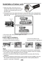
Page 17: ...3mm 3 Remove the wire clip connect the power connection wire to the wiring terminal with wire clip blue brown black yellow green power connection wire cable cross hole 2 Make the power connection wire go through the cable cross hole at the back of indoor unit and then pull it out from the front side Wiring Cover 09 12K 230V 115V N 1 2 Outdoor unit connection N 1 2 3 L1 L2 G 3 18K 24K 230V Notice b...

Page 18: ...eparately at the end Note The power cord and control wire can t be crossed or winding The drain hose should be bound at the bottom drain hose band connection pipe indoor power cord Step nine hang the indoor unit 1 Put the bound pipes in the wall pipe and then make them pass through the wall hole 2 Hang the indoor unit on the wall mounting frame 3 Stuff the gap between pipes and wall hole with seal...

Page 19: ...t should be installed at least in 3cm above the floor in order to install drain joint For the unit with cooling capacity of 2300W 5000W 6 expansion screws are needed for the unit with cooling capacity of 6000W 8000W 8 expansion screws are needed for the unit with cooling capacity of 10000W 16000W 10 expansion screws are needed Step two install drain joint Only for cooling and heating unit 1 Connec...

Page 20: ... bellmouth of pipe 3 Pretightening the union nut with hand 4 Tighten the union nut with torque wrench by referring to the sheet below handle screw gas pipe liquid pipe liquid valve gas valve union nut pipe joint Hex nut diameter Tightening torque N m 30 40 45 55 60 65 70 75 15 20 1 Place the outdoor unit on the support 2 Fix the foot holes of outdoor unit with bolts foot holes foot holes Φ Φ Φ Φ Φ...

Page 21: ...nd heating unit Note Never cut the power connection wire to prolong or shorten the distance The connecting wire and connection pipe cannnot touch each other Handle Indoor unit connection N 1 3 L L N N 2 N 1 L1 L1 L2 L2 3 2 Indoor unit connection Cable Cross Plate Sub assy blue black brown yellow green Install the over line pipe wire pipe Fixed nut Finish GND GND GND GND GND 09 12K 230V 09 12K 115V...

Page 22: ...ain hose can t be fluctuant The drain hose can t be fluctuant The water outlet can t be fluctuant The water outlet can t be placed in water Note Step six neaten the pipes 1 The pipes should be placed along the wall bent reasonably and hidden possibly Min semidiameter of bending the pipe is 4in 10cm 2 If the outdoor unit is higher than the wall hole you must set a U shaped curve in the pipe before ...

Page 23: ... soap water for more than 3min If there are air bubbles coming out of this position there s a leakage Vacuum pumping 1 Remove the valve caps on the liquid valve and gas valve and the nut of refri gerant charging vent 2 Connect the charging hose of piezometer to the refri gerant charging vent of gas valve and then connect the other charging hose to the vacuum pump 3 Open the piezometer com pletely ...

Page 24: ...it grounded securely It may cause electric leakage Does the power cord follow the speci fication It may cause malfunction or damaging the parts Is there any obstruction in the air inlet and outlet It may cause insufficient cooling heating capacity The dust and sundries caused during installation are removed It may cause malfunction or damaging the parts The gas valve and liquid valve of connection...

Page 25: ...longed length of liquid pipe The additional refrigerant charging amount per meter is different according to the diameter of liquid pipe See the following sheet 2 Min length of connection pipe is 9 8ft 3m 3 Max length of connection pipe and max high difference 1 Standard length of connection pipe 16 5ft 5m 25ft 7 5m 26 5ft 8m Cooling capacity Cooling capacity 5000Btu h 1465W 24000Btu h 7032W 7000Bt...

Page 26: ... connection pipe Diameter of connection pipe Liquid pipe in Gas pipe in Φ1 4 Φ1 4 or Φ3 8 Φ3 8 or Φ1 2 Φ1 2 Φ5 8 Φ3 4 Φ7 8 Φ5 8 or Φ3 4 Φ3 4 or Φ7 8 Φ1 or Φ1 _ _ Cooling only g m Cooling and heating g m 15 15 30 60 250 250 350 350 120 120 50 20 Outdoor unit throttle 14 ...

Page 27: ...haper C Put on suitable insulating pipe D Put on the union nut Remove the union nut on the indoor connection pipe and outdoor valve install the union nut on the pipe union pipe pipe E Expand the port Expand the port with expander Note A is different according to the diameter please refer to the sheet below expander hard mold pipe F Inspection Check the quality of expanding port If there is any ble...

Page 28: ...p Thermistor Outdoor Coil Temp Thermistor Compressor Discharge Temp Thermistor Compressor Overload Protection IPM Module Protection Indoor Fan Malfunction Compressor Synchronism 4 Way Valve Malfunction Possible Causes Missing Configuration Jumper on Indoor Control Board Indoor and Outdoor Units Do Not Match Model or Capacity Power Supply is not Stable and Voltage Range is too Large Mis wired or Co...

Page 29: ...ation along with the installation data and dealer contact information will be helpful should your system require maintenance or service www cooperandhunter us PRODUCT INSTALLATION RECORD UNIT INFORMATION Model No Serial No INSTALLATION INFORMATION Date Installed DEALERSHIP INSTALLER INFORMATION Company Name Address Phone Number Technician Name ...

Page 30: ...66162927 Add West Jinji Rd Qianshan Zhuhai Guangdong China 519070 MANUFACTURER GREE ELECTRIC APPLIANCES INC OF ZHUHAI www cooperandhunter us ...

Reviews: