background image

Aliencopter  Studio  All  Rights  Reserved.                                                    www.aliencopter.com 


11

/

31


53 

FA410052  M3 Inner Hexagon Spanner 

54 

FA410053  IMU Foam Double Sided Adhesive Tape 

55 

FA410054  Sticker 

56 

FA410055  Landing Gear Sponge Tube 

57 

FA410056  T Type Slope Indicator 

58 

FA410057  Self Adhansive Tape 

59 

FA410058  Gopro3 Data Cable 

60 

FA410059  Video Transmitter JST Cable 

61 

FA410060  Signal Sheilding Cable 

62 

FA410061  20mm M2.5 Countersun Head Screw 

63 

FA410062  M2.5 shims  

64 

FA410063  M4*7*6mm Nylong Plastic Bolt 

10 

65 

FA410063

M4*7*22mm Nylong Plastic Bolt 

10 

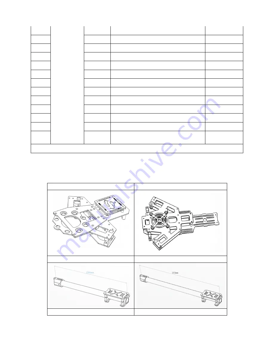
ARF Parts List 

main Component Parts 

Front Frame

×

Back Frame

×


Front Frame 16*236mm Arm

×

Back Frame 16*323mm Arm

×


Link Main Frame 25mm Pipe

×

LiPo Battery Balance 25mm Pipe

×

Summary of Contents for Quad's Flyman

Page 1: ...rved www aliencopter com 1 31 Alien Quad s Flyman User Manual Special Lightweight Multi rotor Helicopters Special Brushless gimbal Customized for Gopro Hero 2 or Hero3 Recommended Camera Gopro Hero3 Gopro Hero2 V1 00 2013 0823 Revision ...

Page 2: ...is disclaimer carefully before using this product By using this product you hereby agree to this disclaimer and signify that you have read them fully Please strictly follow the manual to assemble and use the product The manufacturer and seller assume no liability for any resulting damage or injury arising from the operation or use of this product This product and manual are copyrighted by Aliencop...

Page 3: ...fast protrate foldable frame and collapsible GPS Mount are conveniently portable for optimal user experiences The brushless gimbal had 245 drgree super vision which to create omnidirectional aerial view and high quality photograph Combined with professional multi rotor autopilot system The ALIENCOPTER FLYMAN will achieve hovering cruising and other steady flight elements which can be applied for a...

Page 4: ...rd Step Bartty Package Frame setup 15 The Fourth Step Mount Simple Landing Gear 16 The Final Step Mount Brushless gimbal 17 Attach Electric Equipment to main Frame 20 Install the IMU Mount 20 Install the GPS Video Transmitter Mount 21 Install the Flight control and so on 22 Install the Motor 22 Install the BEC 22 Install The Lipo Bartty 23 Install Gimbal Control Power Supply Hub 23 Full Installed ...

Page 5: ...will be uncontrolled and dangerous Aliencopter studio disclaims all warranties whether express or implied including but not limited to the implied warran ties or merchantability and fitness for a particular purpose Airtechno does not assume any liability whether direct indirect special incidental punitive contingent or consequential damages to persons or property caused by The ALIENCOPTER FLYMAN I...

Page 6: ...ge lines tall trees water etc 3 Make sure to use 4S LiPo battery for power supply 4 Do not get close to or touch the working motors and propellers which will cause serious injury 5 Do not over load the multi rotor 6 Make sure the propellers and the motors are installed correctly and firmly before flying 7 Make sure all parts of product are in good condition before each flight Do not fly with wore ...

Page 7: ...ers and or chafe delicate electronic wires Any time a wire has to make a bend around the carbon fiber booms or frame we recommand using some kind of protective sleeve e g shrink tubing nylon braid etc Carboin fiber is also conductive so it is very important to make sure that a flight components are appropri ately insulated 3 Always remove the props when you are making a change to the configuration...

Page 8: ...ent Speed 6m s Max Flight Velocity 10m s Diagonal distance motor center to motor center 800mm Operating Temperature 10 C to 60 C You have to keep the IMU warm if you want to use it under low temperature could be 10 C or lower Take off Weight 2 5KG 3 5KG Hovering Accuracy GPS Mode Vertical 0 5m Horizontal 2m Max Tilt Angle 35 Max Ascent Descent Speed 6m s Max Flight Velocity 10m s Diagonal distance...

Page 9: ...s Number Type SN Name PCS 1 FA410001 IMU Mount Board 1 2 FA410002 16mm Motor Mount Board 4 3 FA410003 Simple Landing Gear 4 4 FA410004 M3 16mm Motor Mount Carbon Pad 4 5 FA410005 Front Upper Carbon Frame 1 6 FA410006 Front Bottom Carbon Frame 2 7 FA410007 Front Bottom Mount Carbon Plate 1 8 FA410008 Back Upper Carbon Frame 1 9 FA410009 Back Bottom Carbon Pad 1 10 FA410010 25mm Motor Mount Carbon P...

Page 10: ...33 FA410032 25mm Plastic Tube Clip 9 34 FA410033 10mm Silicone Damper 8 35 FA410034 Power Supply Hub 1 36 FA410035 M4 7 30MM Nylong Hex Bolt 12 37 FA410036 8mm M2 5 Countersun Head Screw 6 38 FA410037 6mm M2 5 Countersun Head Screw 20 39 FA410038 14mm M2 5 Countersun Head Screw 8 40 FA410039 30mm M2 5 Countersun Head Screw 28 41 FA410040 M2 5 Hexagon screws 24 42 FA410041 6mm M3 Nylong Screw 8 43 ...

Page 11: ...f Adhansive Tape 1 59 FA410058 Gopro3 Data Cable 1 60 FA410059 Video Transmitter JST Cable 1 61 FA410060 Signal Sheilding Cable 1 62 FA410061 20mm M2 5 Countersun Head Screw 4 63 FA410062 M2 5 shims 4 64 FA410063 M4 7 6mm Nylong Plastic Bolt 10 65 FA410063 1 M4 7 22mm Nylong Plastic Bolt 10 ARF Parts List main Component Parts Front Frame 1 Back Frame 1 Front Frame 16 236mm Arm 2 Back Frame 16 323m...

Page 12: ... Packge Frame 1 Gopro Hero Brushless gimbal 1 Screw parts Kit Tools Needs No Tools name Usage 1 2 00mm Hex Wrench and 2 5mm Hex Wrench For mounting screws 2 Thread Locker For fastening screws 3 Nylon Cable Tie 4 Scissors 5 Diagonal Cutting Pliers 6 Foam Double Sided Adhesive Tape For mounting IMU and so on ...

Page 13: ...Aliencopter Studio All Rights Reserved www aliencopter com 13 31 Main Frame Setup The First step Front Frame Setup ...

Page 14: ...Aliencopter Studio All Rights Reserved www aliencopter com 14 31 The Second Step Back Frame setup ...

Page 15: ...Aliencopter Studio All Rights Reserved www aliencopter com 15 31 The Third Step Bartty Package Frame setup ...

Page 16: ...Aliencopter Studio All Rights Reserved www aliencopter com 16 31 The Fourth Step Mount Simple Landing Gear ...

Page 17: ...bal Gopro Hero 3 needs to be installed in the default installation position If it is Gorpro Hero 2 camera that you choose you can install it by adjusting the screws on the swashplate of the pitching motor as you can see from the image below until the camera reaches a balanced position Based on our experience the screws are usually installed on the upper and rear ...

Page 18: ...Aliencopter Studio All Rights Reserved www aliencopter com 18 31 position to the center of the swashplate ...

Page 19: ... When you install Gopro gimble please make sure that the gravity center of the gimbal suspension arm which is curving at the top is right on the center of the vibration absorption carbon fiber plate Please note that there might be slight differences between the positions of Gopro 2 and Gopro 3 at top as shown in the image below ...

Page 20: ...independent IMU installation The IMU mounting plate needs to be fixed on 4 anti vibration rubber balls the size of which fits most of the flight controls or IMU During installation attention needs to be paid to the direction in which IMU should be installed In the image on the right the triangular arrow icon points to the direction where the aircraft is heading and IMU needs to be installed in the...

Page 21: ... video transmitter needs to be installed with the wire facing the back as in this way under most circumstances it can help prevent the video transmitter from being blocked by the main frame thus expanding the effective transmission range The image on the right shows the installation position and direction of the video transmitter Please use 3M double sided tapes in the Screw Parts kit to hold the ...

Page 22: ...only uses images to demonstrate the main control device installation For other devices you may install according to your own needs Install the Motor During motor installation please make sure to keep the motor flat and the wire outlets facing outside As the following image shows there s a bezel outside the motor set to protect the outlets Install the BEC The BEC installation needs wires connecting...

Page 23: ...a tuned As shown in the image on the right the red arrows indicate the screws that need to be loosed which help tuning the back and forth position of battery after installation The image below shows the innermost of the 25mm carbon fiber tube and the outermost end located two rows of retaining plates The battery we used for testing and tuning is 4S 5800mah LiPo battery Once the battery reaches the...

Page 24: ...Aliencopter Studio All Rights Reserved www aliencopter com 24 31 Full Installed Flyman Frame Below is the image of a Flyman Frame with most of the electric equipment installed for your reference ...

Page 25: ... system respectively You may install the version that is compatible with the operating system you are using 2 Open the gimbal configuration interface select COM port in the dropdown list under Connect tab and then click on connect In normal conditions your PC will successfully connect to the gimbal control board via COM port and read the default parameters Before leaving the factory the optimal pa...

Page 26: ...Aliencopter Studio All Rights Reserved www aliencopter com 26 31 ...

Page 27: ...age below Connect to WiFi hotspot SSID ZERO TECH Default Password 82890430 Once the WiFi connection is established please complete the necessary settings and checks according to YS X4 user manual The link of its official website is http www zerouav com en Product chanpinxilieyi 222 html You can also download the user manual and configure software on AlienCopter s website For the first time install...

Page 28: ...copter com 28 31 Installation Guide on the last slide page of the YS X4 ground station s Set sheet as shown in the image below Please keep testing until the flight control parameters appearing on the ground station get normal as the image below shows ...

Page 29: ...c Declination parameter you need to set the number based on the magnetic declination of your location Take Shenzhen China for instance the Magnetic Declination parameter should be set to 2 0 Cell Number indicates the number of battery cells 4s battery is the type we recommend You may leave other parameter settings as default In the second vertical row you need to set Aircraft Type to Quad Rotor X ...

Page 30: ...uite good at high speed flight and steep turns Its center of gravity is not on the center of the central plate Therefore when it flies steep turns in high speed it needs to make a certain angle In most cases when you flip the direction switch on the remote control you need to add a certain amount of aileron rudder in order to achieve the flight performance similar to the fixed wing aircrafts For t...

Page 31: ...Aliencopter Studio All Rights Reserved www aliencopter com 31 31 Appendix ...

Reviews: