background image

UPMIDIAS

Removing 

the 

Display 

Panel  |  

69

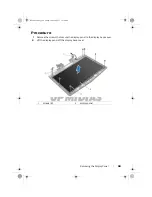
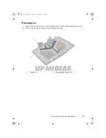
Procedure

1

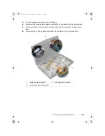
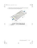
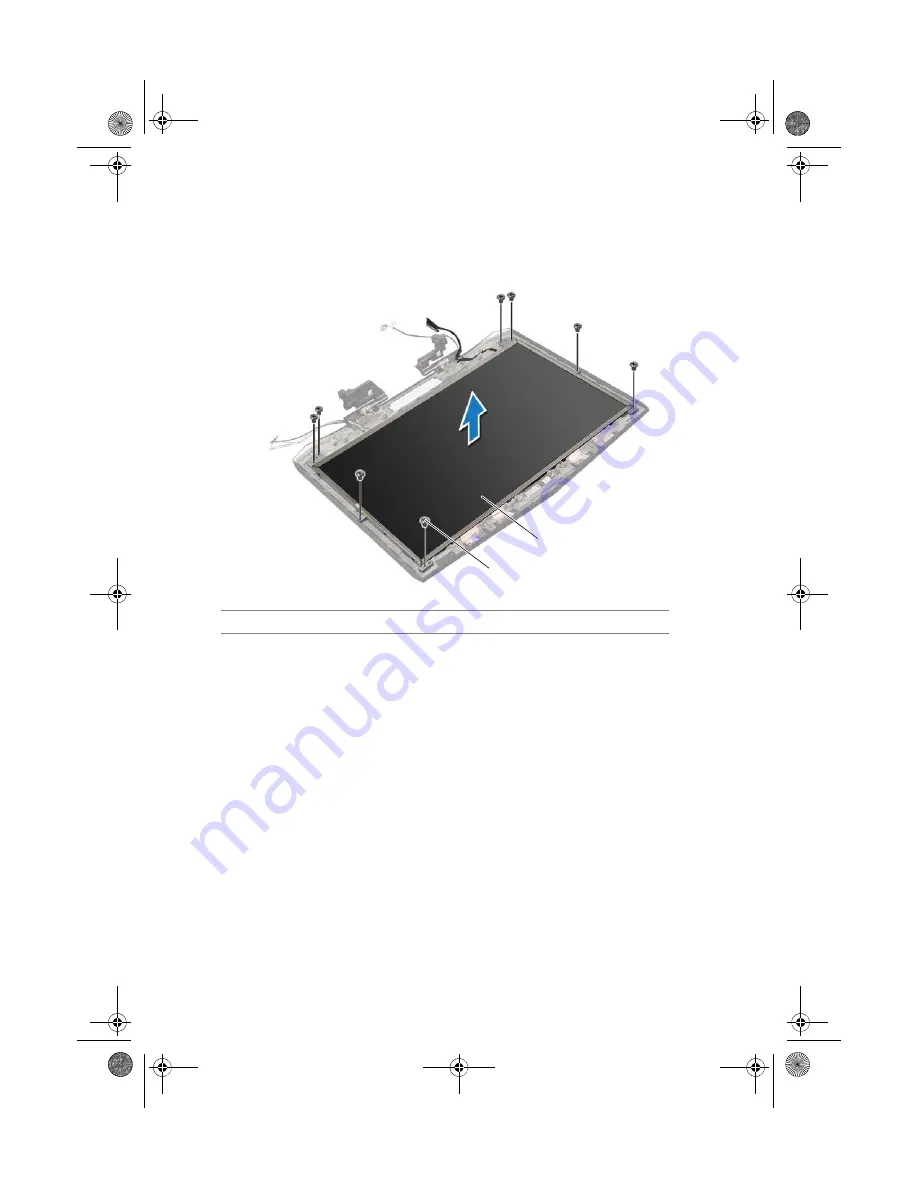
Remove the screws that secure the display panel to the display back-cover.

2

Lift the display panel off the display back-cover.

1

screws (8)

2

display panel

1

2

Book.book  Page 69  Friday, June 28, 2013  11:10 AM

Summary of Contents for 18 P19E

Page 1: ...o o unidad de estado s lido 14 Lector de tarjetas multimedia 15 Teclado retroiluminado 16 Panel t ctil retroiluminado 17 Un puerto combo de aud fono micr fono 18 Puerto de aud fonos altavoces 19 Puert...

Page 2: ...v a con el equipo Para obtener informaci n sobre las mejores pr cticas de seguridad consulte dell com regulatory_compliance Switch to external display Bascule vers moniteur externe Cambiar a la pantal...

Page 3: ...UPMIDIAS Alienware 18 Owner s Manual Computer model Alienware 18 Regulatory model P19E Regulatory type P19E001 Book book Page 1 Friday June 28 2013 11 10 AM...

Page 4: ...Inc is strictly forbidden Trademarks used in this text Alienware and the AlienHead logo are trademarks or registered trademarks of Alienware Corporation Dell is a trademark of Dell Inc Microsoft Windo...

Page 5: ...e Base Cover 15 Procedure 15 Postrequisites 15 Removing the Battery Pack 16 Procedure 16 Replacing the Battery Pack 17 Procedure 17 Postrequisites 17 Removing the Memory Module s 18 Prerequisites 18 P...

Page 6: ...ing the Video Card Heat Sink Fan s 31 Prerequisites 31 Procedure 31 Replacing the Video Card Heat Sink Fan s 33 Procedure 33 Postrequisites 33 Removing the Processor Heat Sink Fan 34 Prerequisites 34...

Page 7: ...requisites 44 Removing the Power Button Board 45 Prerequisites 45 Procedure 45 Replacing the Power Button Board 46 Procedure 46 Postrequisites 46 Removing the Status Light Board 47 Prerequisites 47 Pr...

Page 8: ...ocedure 60 Postrequisites 60 Removing the Camera Module 61 Prerequisites 61 Procedure 62 Replacing the Camera Module 63 Procedure 63 Postrequisites 63 Removing the Display Bezel 64 Prerequisites 64 Pr...

Page 9: ...ure 75 Postrequisites 75 Removing the Display Light Boards 76 Prerequisites 76 Procedure 77 Replacing the Display Light Boards 78 Procedure 78 Postrequisites 78 Removing the Speakers 79 Prerequisites...

Page 10: ...ure 90 Postrequisites 90 Removing the Video Card s 91 Prerequisites 91 Procedure 91 Replacing the Video Card s 93 Procedure 93 Postrequisites 93 Removing the Processor Heat Sink 94 Prerequisites 94 Pr...

Page 11: ...Service Tag in the BIOS 104 Removing the Wireless Mini Card 105 Prerequisites 105 Procedure 106 Replacing the Wireless Mini Card 107 Procedure 107 Postrequisites 108 System Setup 109 Overview 109 Ent...

Page 12: ...UPMIDIAS 10 Contents Book book Page 10 Friday June 28 2013 11 10 AM...

Page 13: ...corner of the screen to open the Charms sidebar and then click Settings Power Shut Down Microsoft Windows shuts down and then the computer turns off Windows 7 Click Start and click Shut down NOTE If...

Page 14: ...instructions for complete information about safety precautions working inside your computer and protecting against electrostatic discharge CAUTION Before touching anything inside your computer ground...

Page 15: ...nside your computer Connect any external devices cables cards and any other part s you removed before working on your computer Connect your computer and all attached devices to their electrical outlet...

Page 16: ...fore You Begin on page 11 For additional safety best practices information see the Regulatory Compliance Homepage at dell com regulatory_compliance Procedure 1 Remove the screws that secure the base c...

Page 17: ...al safety best practices information see the Regulatory Compliance Homepage at dell com regulatory_compliance Procedure 1 Align the tabs on the base cover with the slots on the computer base and slide...

Page 18: ...es information see the Regulatory Compliance Homepage at dell com regulatory_compliance Prerequisites Remove the base cover See Removing the Base Cover on page 14 Procedure 1 Remove the screws that se...

Page 19: ...o avoid damage to the computer use only the battery designed for this particular Alienware computer Procedure 1 Align the tabs on the battery with the slots on the computer base and place the battery...

Page 20: ...Regulatory Compliance Homepage at dell com regulatory_compliance NOTE Your computer supports up to four memory module connectors You can access connectors DIMM3 and DIMM4 by removing the base cover a...

Page 21: ...on page 39 CAUTION To prevent damage to the memory module connector do not use tools to spread the memory module securing clips 3 Using your fingertips spread apart the securing clips on each end of t...

Page 22: ...the base cover at the bottom of your computer You can access connectors DIMM1 and DIMM2 by removing the palmrest Procedure NOTE If you need to install memory modules in two connectors install a memory...

Page 23: ...le s in connectors DIMM1 and DIMM2 Replace the palm rest See Replacing the Palm Rest on page 42 Postrequisites 1 Replace the battery pack See Replacing the Battery Pack on page 17 2 Replace the base c...

Page 24: ...age at dell com regulatory_compliance Prerequisites 1 Remove the base cover See Removing the Base Cover on page 14 2 Remove the battery pack See Removing the Battery Pack on page 16 Procedure 1 Discon...

Page 25: ...hat secure the optical drive bracket to the optical drive 5 Lift the optical drive bracket off the optical drive 6 Remove the interposer from the optical drive 1 optical drive bracket 2 interposer 3 s...

Page 26: ...he screw holes on the optical drive and replace the screws that secure the optical drive bracket to the optical drive 3 Align the slot on the optical drive with the alignment posts on computer base an...

Page 27: ...nformation see the Regulatory Compliance Homepage at dell com regulatory_compliance CAUTION To avoid data loss do not remove the hard drive while the computer is in Sleep or On state CAUTION Hard driv...

Page 28: ...r on the system board 2 Loosen the captive screws that secure the hard drive assembly to the computer base 3 Using the pull tab lift the hard drive assembly out of the computer base 1 hard drive cable...

Page 29: ...d drives NOTE Your computer supports up to three drives 5 Remove the screws that secure the hard drive s to the hard drive bracket and slide the hard drive s out of the hard drive bracket 1 hard drive...

Page 30: ...ews that secure the primary hard drive to the hard drive bracket 4 If applicable replace the screws that secure the secondary hard drive to the hard drive bracket 5 Connect the interposer to the hard...

Page 31: ...n on page 11 For additional safety best practices information see the Regulatory Compliance Homepage at dell com regulatory_compliance Prerequisites 1 Remove the base cover See Removing the Base Cover...

Page 32: ...ion see the Regulatory Compliance Homepage at dell com regulatory_compliance Procedure Align the tabs on the fans cover with the slots on the computer base and slide the fans cover into place Postrequ...

Page 33: ...iance Prerequisites 1 Remove the base cover See Removing the Base Cover on page 14 2 Remove the battery pack See Removing the Battery Pack on page 16 3 Remove the fans cover See Removing the Fans Cove...

Page 34: ...oard 4 Loosen the captive screws that secure the secondary video card heat sink fan to the computer base 5 Lift the video card heat sink fan s along with the cable away from the computer base 1 captiv...

Page 35: ...eat sink fan to the computer base 3 Tighten the captive screws that secure the primary video card heat sink fan to the computer base 4 Route the primary video card heat sink fan cable through the rout...

Page 36: ...isites 1 Remove the base cover See Removing the Base Cover on page 14 2 Remove the battery pack See Removing the Battery Pack on page 16 3 Remove the fans cover See Removing the Fans Cover on page 29...

Page 37: ...rew holes on the processor heat sink fan with the screw holes on the computer base 2 Tighten the captive screws that secure the processor heat sink fan to the computer base 3 Connect the processor hea...

Page 38: ...ctrical outlet for a few hours then reconnect the computer turn it on and enter system setup If the date and time are not correct in system setup replace the coin cell battery You can operate your com...

Page 39: ...from its connector on the system board 2 Remove the coin cell battery cable from the routing guides on the computer base 3 Pry up the coin cell battery from the slot on the system board 1 coin cell b...

Page 40: ...Discard used batteries according to the manufacturer s instructions Procedure 1 Place the coin cell battery into the slot and press gently to adhere it to the computer base 2 Route the coin cell batt...

Page 41: ...omepage at dell com regulatory_compliance Prerequisites 1 Remove any installed card or blank from the Media Card Reader 2 Remove the base cover See Removing the Base Cover on page 14 3 Remove the batt...

Page 42: ...Lift the connector latches and pull the pull tabs to disconnect the macro keyboard cable and macro keyboard backlight cable from the connectors on the system board 3 Remove the screws that secure the...

Page 43: ...om the computer base CAUTION Carefully separate the palmrest from the computer base to avoid damage to the palmrest 6 Lift the palm rest assembly off the computer base 7 Remove the status light board...

Page 44: ...ter base 5 Slide the media card reader cable and keyboard cable into the respective connectors on the palm rest assembly and press down on the connector latches to secure the cables 6 Slide the macro...

Page 45: ...latory Compliance Homepage at dell com regulatory_compliance Prerequisites 1 Remove the base cover See Removing the Base Cover on page 14 2 Remove the battery pack See Removing the Battery Pack on pag...

Page 46: ...ance Procedure 1 Insert the mSATA card connector at a 45 degree angle into the system board connector 2 Press the other end of the mSATA card down into the slot on the system board and replace the scr...

Page 47: ...ver See Removing the Fans Cover on page 29 4 Remove the battery pack See Removing the Battery Pack on page 16 5 Remove the hard drive See Removing the Hard Drive s on page 25 6 Remove the optical driv...

Page 48: ...the power button board cable into its connector on the status light board and press down on the connector latch to secure the cable 4 Follow the instructions from step 3 to step 6 in Replacing the Pal...

Page 49: ...ry_compliance Prerequisites 1 Remove any installed card or blank from the Media Card Reader 2 Remove the base cover See Removing the Base Cover on page 14 3 Remove the fans cover See Removing the Fans...

Page 50: ...ble and media card reader cable from the connectors on the status light board 2 Remove the screws that secure the status light board to the palm rest assembly 3 Lift the status light board off the pal...

Page 51: ...e power button board cable and media card reader cable into the respective connectors on the status light board and press down on the connector latches to secure the cables 4 Follow the instructions f...

Page 52: ...nce Prerequisites 1 Remove any installed card or blank from the Media Card Reader 2 Remove the base cover See Removing the Base Cover on page 14 3 Remove the fans cover See Removing the Fans Cover on...

Page 53: ...N Be extremely careful when removing and handling the keyboard Failure to do so could result in scratching the display panel Lift the connector latches and pull the pull tabs to disconnect the media c...

Page 54: ...he pull tab to disconnect the keyboard cable from the respective connector 4 Remove the screws that secure the keyboard to the palm rest assembly 5 Lift the keyboard off the palm rest assembly 1 screw...

Page 55: ...dia card reader cable and keyboard backlight cable into their respective connectors and press down on the connector latches to secure the cables 6 Replace the screws that secure the keyboard bracket t...

Page 56: ...See Removing the Battery Pack on page 16 2 Remove the base cover See Removing the Base Cover on page 14 3 Remove the keyboard See Removing the Keyboard on page 50 Procedure 1 Remove the screw that sec...

Page 57: ...pliance Procedure 1 Slide the tab on the macro keyboard into the slot on the palm rest assembly and lower the macro keyboard into place 2 Replace the screw that secures the macro keyboard to the compu...

Page 58: ...Media Card Reader 2 Remove the base cover See Removing the Base Cover on page 14 3 Remove the fans cover See Removing the Fans Cover on page 29 4 Remove the battery pack See Removing the Battery Pack...

Page 59: ...m its connector on the system board 5 Pull the pull tab to disconnect the display cable from its connector on the system board 6 Disconnect the LED logo board cable from its connector on the system bo...

Page 60: ...page 105 8 Note the routing of the antenna cables and then remove the cables from the routing guides on the computer base 9 Remove the screw that secures the routing guides to the computer base 10 Sli...

Page 61: ...display hinges that secure the display assembly to the computer base 12 Move the display to a perpendicular position to the computer base and then lift the display assembly off the computer 1 display...

Page 62: ...bles to the Mini Card See Replacing the Wireless Mini Card on page 107 5 Connect the display cable video card connector cable and LED logo board cable to the respective connectors on the system board...

Page 63: ...ia Card Reader 2 Remove the base cover See Removing the Base Cover on page 14 3 Remove the fans cover See Removing the Fans Cover on page 29 4 Remove the battery pack See Removing the Battery Pack on...

Page 64: ...ures the camera module to the display back cover 2 Disconnect the camera cable from the camera module connector 3 Pry and lift the camera module off the display back cover 1 screw 1 2 camera module 3...

Page 65: ...1 Replace the display bezel See Replacing the Display Bezel on page 65 2 Replace the display assembly See Replacing the Display Assembly on page 60 3 Follow the instructions from step 3 to step 6 in...

Page 66: ...oving the Base Cover on page 14 3 Remove the fans cover See Removing the Fans Cover on page 29 4 Remove the battery pack See Removing the Battery Pack on page 16 5 Remove the hard drive s See Removing...

Page 67: ...e the display assembly See Replacing the Display Assembly on page 60 2 Follow the instructions from step 3 to step 6 in Replacing the Palm Rest 3 Replace the optical drive See Replacing the Optical Dr...

Page 68: ...he fans cover See Removing the Fans Cover on page 29 4 Remove the battery pack See Removing the Battery Pack on page 16 5 Remove the hard drive s See Removing the Hard Drive s on page 25 6 Remove the...

Page 69: ...ce the display bezel See Replacing the Display Bezel on page 65 2 Replace the display assembly See Replacing the Display Assembly on page 60 3 Follow the instructions from step 3 to step 6 in Replacin...

Page 70: ...a Card Reader 2 Remove the base cover See Removing the Base Cover on page 14 3 Remove the fans cover See Removing the Fans Cover on page 29 4 Remove the battery pack See Removing the Battery Pack on p...

Page 71: ...ay Panel 69 Procedure 1 Remove the screws that secure the display panel to the display back cover 2 Lift the display panel off the display back cover 1 screws 8 2 display panel 1 2 Book book Page 69 F...

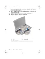
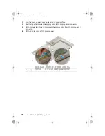
Page 72: ...face 4 Peel the tape that secures the display cable to the display panel connector 5 Lift the connector latch and disconnect the display cable from the display panel connector 6 Lift the display cable...

Page 73: ...Remove the screws that secure the display panel brackets to the display panel 8 Slide the display panel brackets off the display panel 1 screws 6 2 display panel brackets 3 display panel 1 2 3 Book b...

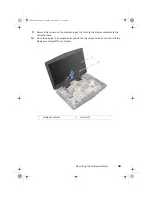
Page 74: ...holes on the display back cover 6 Replace the screws that secure the display panel to the display back cover Postrequisites 1 Replace the display hinges See Replacing the Display Hinges on page 67 2...

Page 75: ...14 3 Remove the fans cover See Removing the Fans Cover on page 29 4 Remove the battery pack See Removing the Battery Pack on page 16 5 Remove the hard drive s See Removing the Hard Drive s on page 25...

Page 76: ...display back cover 2 Carefully rotate the logo board over and disconnect the display light board cables from the connectors on the logo board 3 Lift the logo board off the display back cover 1 screws...

Page 77: ...Replacing the Display Panel on page 72 2 Replace the display hinges See Replacing the Display Hinges on page 67 3 Replace the display bezel See Replacing the Display Bezel on page 65 4 Replace the dis...

Page 78: ...See Removing the Fans Cover on page 29 4 Remove the battery pack See Removing the Battery Pack on page 16 5 Remove the hard drive s See Removing the Hard Drive s on page 25 6 Remove the optical drive...

Page 79: ...77 Procedure 1 Remove the screws that secure the display light boards to the display back cover 2 Lift the display light boards off the display back cover 1 screws 5 2 display light boards 3 2 1 Book...

Page 80: ...lacing the Display Panel on page 72 3 Replace the display hinges See Replacing the Display Hinges on page 67 4 Replace the display bezel See Replacing the Display Bezel on page 65 5 Replace the displa...

Page 81: ...nce Prerequisites 1 Remove any installed card or blank from the Media Card Reader 2 Remove the base cover See Removing the Base Cover on page 14 3 Remove the fans cover See Removing the Fans Cover on...

Page 82: ...able routing and remove the cable from the routing guides on the computer base 3 Remove the screws that secure the speakers to the computer base 4 Lift the speakers along with the speaker cable off th...

Page 83: ...e routing guides on the computer base and then connect the speakers cable to its connector on the system board Postrequisites 1 Follow the instructions from step 3 to step 6 in Replacing the Palm Rest...

Page 84: ...on that shipped with your computer and follow the steps in Before You Begin on page 11 For additional safety best practices information see the Regulatory Compliance Homepage at dell com regulatory_co...

Page 85: ...ing and remove the cable from the routing guides on the computer base 3 Loosen the captive screws that secure the subwoofer to the computer base 4 Lift the subwoofer along with the subwoofer cable off...

Page 86: ...compliance Procedure 1 Align the screw holes on the subwoofer with the screw holes on the computer base 2 Tighten the captive screws that secure the subwoofer to the computer base 3 Route the subwoofe...

Page 87: ...liance Prerequisites 1 Remove any installed card or blank from the Media Card Reader 2 Remove the base cover See Removing the Base Cover on page 14 3 Remove the fans cover See Removing the Fans Cover...

Page 88: ...ct sensor board cable from its connector on the sound board 2 Remove the screws that secure the sound board to the computer base 3 Gently lift the sound board out of the slots on the computer base 1 s...

Page 89: ...board cable into its connector on the sound board and press down on the connector latch to secure the cable Postrequisites 1 Follow the instructions from step 3 to step 6 in Replacing the Palm Rest 2...

Page 90: ...3 Remove the fans cover See Removing the Fans Cover on page 29 4 Remove the battery pack See Removing the Battery Pack on page 16 5 Remove the hard drive See Removing the Hard Drive s on page 25 6 Re...

Page 91: ...Heat Sink s 89 Primary video card heat sink Secondary video card heat sink 1 primary video card heat sink 2 captive screws 4 1 captive screws 4 2 secondary video card heat sink 1 2 1 2 Book book Page...

Page 92: ...ink to the video card 3 Tighten the captive screws that secure the secondary video card heat sink to the video card Postrequisites 1 Replace the video card s See Replacing the Video Card s on page 93...

Page 93: ...the base cover See Removing the Base Cover on page 14 3 Remove the fans cover See Removing the Fans Cover on page 29 4 Remove the battery pack See Removing the Battery Pack on page 16 5 Remove the ha...

Page 94: ...system board 4 Lift and slide the video card s along with heat sink s out to disconnect it from the connectors on the system board Primary Video Card Secondary Video Card 1 primary video card 2 screw...

Page 95: ...secure the video card s to the system board 3 Connect the video card connector cable to the connectors on the system board Postrequisites 1 Replace the display assembly See Replacing the Display Assem...

Page 96: ...fans cover See Removing the Fans Cover on page 29 4 Remove the battery pack See Removing the Battery Pack on page 16 5 Remove the hard drive s See Removing the Hard Drive s on page 25 6 Remove the opt...

Page 97: ...e Align the captive screws on the processor heat sink with the screw holes on the system board and tighten the screws in sequential order indicated on the processor heat sink Postrequisites 1 Replace...

Page 98: ...es 1 Remove any installed card or blank from the Media Card Reader 2 Remove the base cover See Removing the Base Cover on page 14 3 Remove the fans cover See Removing the Fans Cover on page 29 4 Remov...

Page 99: ...processor module do not touch the heat transfer areas on the processor thermal cooling assembly The oils in your skin can reduce the heat transfer capability of the thermal pads CAUTION When removing...

Page 100: ...ure 1 Align the pin 1 corner of the processor module with the pin 1 corner of the ZIF socket then place the processor module NOTE The pin 1 corner of the processor module has a triangle that aligns wi...

Page 101: ...l drive See Replacing the Optical Drive on page 24 5 Replace the hard drive s See Replacing the Hard Drive s on page 28 6 Replace the battery pack See Replacing the Battery Pack on page 17 7 Replace t...

Page 102: ...ck on page 16 5 Remove the memory modules See Removing the Memory Module s on page 18 6 Remove the hard drive s See Removing the Hard Drive s on page 25 7 Remove the optical drive See Removing the Opt...

Page 103: ...from the connectors on the system board 2 Lift the connector latch and disconnect the tron light cables from the connectors on the system board 1 tron lights cable 1 2 tron lights cable 2 3 tron ligh...

Page 104: ...t secure the system board to the computer base 4 Carefully ease the connectors on the system board out of the slots in the computer base and lift the system board off the computer base 1 screws 8 2 sy...

Page 105: ...g the Wireless Mini Card on page 107 4 Replace the mSATA card See Replacing the mSATA Card on page 44 5 Replace the video card s See Replacing the Video Card s on page 93 6 Replace the video card heat...

Page 106: ...rom the Media Card Reader 19 Follow the instructions in After Working Inside Your Computer on page 13 Entering the Service Tag in the BIOS 1 Turn on the computer 2 Press F2 during POST to enter the sy...

Page 107: ...ni Card with your computer the card is already installed Your computer has one half Mini Card slot which supports a Wireless Local Area Network WLAN Bluetooth combo card Prerequisites 1 Remove any ins...

Page 108: ...rom the connectors on the wireless Mini Card 2 Remove the screw that secures the wireless Mini Card to the system board 3 Lift the wireless Mini Card away from the system board connector 1 antenna cab...

Page 109: ...e wireless Mini Card and on the system board and realign the wireless Mini Card CAUTION To avoid damage to the wireless Mini Card never place cables under the wireless Mini Card 2 Insert the wireless...

Page 110: ...ee Replacing the Hard Drive s on page 28 4 Replace the battery pack See Replacing the Battery Pack on page 17 5 Replace the fans cover See Replacing the Fans Cover on page 30 6 Replace the base cover...

Page 111: ...ystem setup it is recommended that you write down the system setup screen information for future reference Entering System Setup 1 Turn on or restart your computer 2 During POST when the ALIENWARE log...

Page 112: ...eld appears on the right side of the system setup window and contains information about each option listed in the Setup Item In this field you can view information about your computer and make changes...

Page 113: ...A device installed AC Adapter Type Displays the type of AC adapter connected to your computer Total Memory Displays the total memory available in your computer Memory Bank 0 Displays the memory size i...

Page 114: ...devices to wake the computer from standby or to disable the USB wake support feature NOTE If USB PowerShare is enabled a device connected to the USB PowerShare connector may not wake the computer SAT...

Page 115: ...o Flex Support Allows you to enable or disable non turbo flex support Flex Ratio Override Allows you to set the flex ratio override value Extreme Edition Allows you to disable or choose BIOS or cTDP E...

Page 116: ...l Bluetooth device Disabled The internal Bluetooth device is disabled and is not visible to the operating system Enabled The internal Bluetooth device is enabled Wireless Network Allows you to enable...

Page 117: ...t Load Legacy Option Rom Allows you to enable or disable the option to load a legacy Rom NOTE This option is disabled when Secure Boot option is enabled Boot List Option Allows you to set the boot seq...

Page 118: ...otable the computer generates an error message Second Hard Drive The computer attempts to boot from the secondary hard drive If no operating system is on the drive the computer generates an error mess...

Page 119: ...an error message Second Hard Drive The computer attempts to boot from the secondary hard drive If no operating system is on the drive the computer generates an error message eSATA The computer attempt...

Page 120: ...or restart your computer 2 During POST when the DELL logo is displayed watch for the F2 prompt to appear and then press F2 immediately NOTE The F2 prompt indicates that the keyboard has initialized Th...

Page 121: ...ne of the following options Automatically detect my Service Tag for me Choose from My Products and Services List Choose from a list of all Dell products b Click Continue and follow the instructions on...

Reviews: