CHAPTER 4: INSTALLING AND REPLACING COMPONENTS
61
2
1
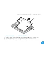
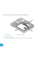
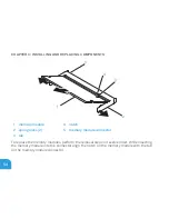
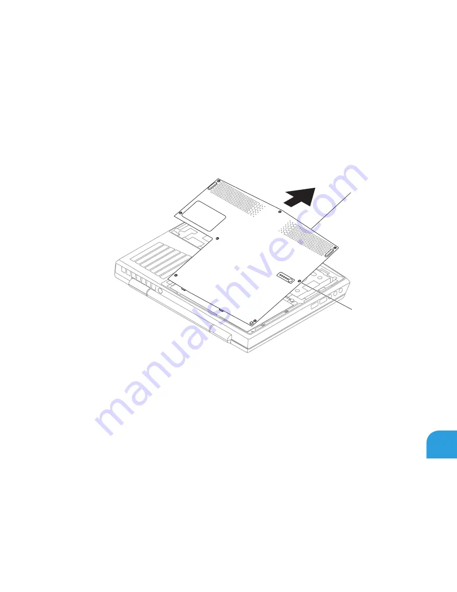
1 captive screws (8)
2 compartment door
Loosen the two captive screws that secure the battery pack to the computer base.
5.
Disconnect the battery pack cable from the connector on the system board.
6.
Lift and slide the battery pack out of the computer.
7.
Summary of Contents for Alienware DRF37
Page 1: ...ALIENWARE M11x MOBILE MANUAL...
Page 6: ...6...
Page 8: ...8...
Page 9: ...CHAPTER 1 SETTING UP YOUR LAPTOP CHAPTER 1 SETTING UP YOUR LAPTOP...
Page 13: ...CHAPTER 1 SETTING UP YOUR LAPTOP 13 Press the Power Button...
Page 14: ...CHAPTER 1 SETTING UP YOUR LAPTOP 14 Connect the Network Cable Optional...
Page 19: ...CHAPTER 2 GETTING TO KNOW YOUR LAPTOP CHAPTER 2 GETTING TO KNOW YOUR LAPTOP...
Page 25: ...CHAPTER 2 GETTING TO KNOW YOUR LAPTOP 25...
Page 26: ...CHAPTER 2 GETTING TO KNOW YOUR LAPTOP 26 Display Features 1 2 3 4...
Page 28: ...CHAPTER 2 GETTING TO KNOW YOUR LAPTOP 28 Computer Base and Keyboard Features 2 3 4 1...
Page 35: ...CHAPTER 3 USING YOUR LAPTOP CHAPTER 3 USING YOUR LAPTOP...
Page 55: ...CHAPTER 4 INSTALLING AND REPLACING COMPONENTS CHAPTER 4 INSTALLING AND REPLACING COMPONENTS...
Page 69: ...CHAPTER 5 TROUBLESHOOTING CHAPTER 5 TROUBLESHOOTING...
Page 83: ...CHAPTER 6 SYSTEM RECOVERY CHAPTER 6 SYSTEM RECOVERY...
Page 88: ...CHAPTER 6 SYSTEM RECOVERY 88...
Page 89: ...CHAPTER 7 BASIC SPECIFICATIONS CHAPTER 7 BASIC SPECIFICATIONS...
Page 95: ...APPENDIX APPENDIX...


